I am very pleased to have discovered this group, and have the utmost
respect for the participants and their obvious expertise. One of the
first things I saw was the 555 injector control.
I have been planning for several weeks to use the 555 injector
system on
my project, so I was entering the schematic in preparation for laying
out the circuit board. I was considering how to make provision for the
initial setup when I realized the MAF sensor output is related to air
mass per unit of time, whereas the 555 controls fuel mass per firing
cycle. There is not a defined correspondence between the two except
for
a fixed engine speed..
Assume an engine running wide-open-throttle (WOT) at 4000 rpm, and the
555 delivering the proper pulse width for proper fuel delivery. Lower
the nose and allow the engine to advance to 6000 rpm. The airflow
increases by 50%, and the MAF sensor output increases 50%, lengthening
the pulse by 50%. Because of the increase in rpm, there are 50% more
pulses, each of which injects 50% more fuel, for an increase to 225%
of
the original flow instead of the desired 150%. In fact, absent a
change
in volumetric efficiency between the two rpm settings, the pulse width
should not change, but deliver the same amount of fuel per
combustion cycle.
Fortunately there is a simple solution. The integral of the 555 output
is proportional to fuel flow per unit of time. The mass of fuel flow
per
unit time (instead of per revolution) is easily obtained by
multiplying
the flow capacity of the injector by the duty cycle of the 555. Duty
cycle is determined by the duration of the 555 pulse and the frequency
of the trigger (a direct function of rpm), and is represented by the
average voltage on the 555 output divided by the 555 output "HIGH"
voltage.
By connecting a resistor from the output of the 555 to the inverting
input of the TLC279 op amp and a capacitor from that input to ground,
the average voltage is presented to that input. The op amp now
compares
the (mass airflow)/time to the (mass fuel flow)/time, and generates an
output to control the pulse width. It then becomes a matter of
determining the correct component values to set the 555 timer
characteristics and the op amp gain for the injectors and MAF sensor
used.
A variable resistor would still be used to allow the pilot to alter
the
mixture would still be desired, but the system would automatically
compensate for volumetric efficiency variations with rpm, because it
would always maintain a fixed relationship between the air and fuel
volumes (aside from injector latency, fuel pressure variations,
etc.) We
are obviously not measuring fuel flow directly, but are measuring
directly the command to the injector. Installation-specific
adjustments
would be required for idle and full power, but everything in between
would be automatic.
Victor Roberts
With all due respect I don't think you are right.
This is just a rough approx. to keep the engine running over the
rev range.
The VE also changes with RPM. It can go from 100% to 120% over a
2000 RPM
change in a organ pipe tuned system.
I would not use a 555 system in a car
as it will not tune the engine properly over a wide range of HP, RPM
and load combinations under transient conditions. You also might not
want to
use the 555 system in an aerobatic airplane.
I Think you have to go from a high angle climb to a vertical dive to
get
the engine to rev from 4000 full load to 6000 full load. I think
that is an
unrealistic scenario for most aircraft. The prop load changes a lot
over such a wide range during normal operation. The fixed pitch prop
load
is the square or cube of RPM. The engine RPM might change
several hundread RPM in a cruise situation but then you must adjust
the leaning just like any other aircraft engine.
BTW The rotary unlike an aircraft engine will run over an air fuel
mixture ratio of 10:1 to 20:1.
Paul Lamar
Paul, Victor -
Victor is right that with an Inject-Per-Revolution scheme (IPR - I
made it up), a simple MAF sensor/555 timer would need some RPM
feedback and compensation, making it ... not simple.
Paul is wrong that it should be designed/built as "just a rough approx
just keep the engine running". It should be designed to match the
fuel injected to the incoming air.
Paul is right that VE can change. However it can change for the worse
over a given RPM range as easily as it can change for the better. IPR
schemes need crank angle and RPM feedback to work effectively,
otherwise the air/fuel ratio will be all over the map (no pun intended).
I had always assumed that the 555 timer would inject independent of
RPM or crank angle. The injectors would sit upstream enough in the
manifold, happily injecting away in fine grained pulses, so the fuel
ingested per intake stroke would average out and only slightly vary.
This would be an Inject-Over-Time scheme (IOT - I made that up, too).
NOTE: That is the beauty of MAF sensors - they tell you the amount of
air going in - you simply inject a matching ratio of fuel, and it'll
burn at 350 RPM, 4000 RPM, or 6500 RPM - hence the simplicity of the
555 timer for controlling fuel injector pulse width.
BUT... If you're going to start varying the injection RATE (tied to
crank angle/RPM), then you need to COMPENSATE the fuel pulse width
with the same variable (RPM), in a feedback to the FORMERLY simple
system.
Paul - just have the 555 Timer system inject in a relatively fast
pulse stream independent of the RPM/crank angle, using the IOT scheme.
In other words, keep it simple. (Just my 2 cents worth.)
-Vince Orton
I you think it will work that scheme solves a lot of problems with
high speed
injection. There is not a lot of time to inject fuel once per rev at
7500 RPM
anyway. All we need is an oscillator to trigger the 555's.
It does make it a lot simpler as we don't need injection triggers
and the associated
circuits. I am getting close to trying the 555 system as the RX8
engine slide throttle
and intake tubes are near done. The motor mount is done and the prop
dyno is near done.
Paul Lamar
This works in theory but not in practice because of the latency (delay
between the leading edge of the pulse and the beginning of fuel flow) of
the injectors. In order to get even distribution from one firing cycle
to the next, there would need to be at least 3 pulses per firing cycle
at the highest rpm. The injectors can't work that fast. I am planning
to use the spark trigger as the start of the injection cycle, as
injector timing is not critical. At low rpm this is not optimum, but is
works fine for higher rpm. Using one sensor for each injector/spark plug
gives four independent ignition/injection systems for a two-rotor. If a
sensor fails, it takes out only the related injector/plug. Turn the
mixture full rich and the rotor with the failed sensor runs lean but
still produces power, and the other rotor runs rich. Good for limp-home.
To Craig Taylor - I'm not an engineer, just a guy who spent 45 years
working on airplanes and longer than that on electronics. I used to tell
my technicians that a technician only need to know what direction a
change would go, but an engineer could tell you how far. In that regard,
could you tell us the minimum time constant needed for a simple RC
filter to provide feedback to the inverting input of the op amp as
depicted in the schematic for the leaning system for operation from 1500
to 7500 rpm?
Victor Roberts
The latency delay is only about 1 ms. The large variations are down in
the idle range 1 to 3 MS. I don't see that as a show stopper. We idle
the engine at 2000 RPM due to gear box rattle.
The wcf file needs to be converted to a jpg or gif to publish.
Paul Lamar
Hi all.
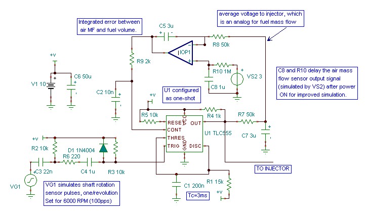
This is a quick pass at the design using an average of the injector voltage as an analog of the fuel volume. It
compares the air mass flow to the fuel volume flow and adjusts the fuel flow (via Control on the 555) to force the fuel
to match the air flow. The signals are summed in the integrator made up of the opamp IOP1 and C5, R8.
I ran a simulation to make sure it was stable. The injector pulse smoothing filter values ( R7 and C7) are
approximate, but they shouldn't be critical. Since the constant pulse width, one pulse per rev approach gives a first
approximation of the fuel requirements of the engine, allowing 1 second or more for the feedback loop to adjust to the
new MAF sensor voltage shouldn't be an issue.
For an actual system, somel component values need to be optimized. I used 15k and 200nF for the one shot RC time
constant. For a 555, the RC product of the components is very close to the actual pulse width; here it's 1.5E4 Ohms x
2E-7 Farads= 3E-3 seconds= 3ms.
That means that when the Control voltage is 2/3 of the supply voltage (6.66V in my case) the output pulse is 3ms.
This base value can be easily adjusted by varying R1.
You should be aware that increasing Control voltage above about 0.95xVsupply will cause strange things to happen.
So shouldn't make that voltage part of the normal operating range. Therefore I would pick RC to be the middle of the
expected injector pulse width range. That allows Control to adjust the pulse width over a reasonable range.
Also note that I haven't make any attempt to "calibrate" the system. I have no idea, for instance, what full scale (
5V? ) on the MAF sensor output is equal to expected full speed-full throttle air flow. I don't even know if the MAF
sensor output is LINEAR with air mass flow. I sure hope so!
Craig Taylor
--
The Rotary Engine NewsLetter. Powered by Linux.
ACRE NL web site.
http://www.rotaryeng.net
Youtube key word UTUBPLEASE
Copyright 1998-2009 All world wide rights reserved.