-SNIP-
Why? I don't follow your reasoning? Are you referring to Paul Yaw's data?
If so which chart?
Paul Lamar
Yes, Paul Yaw's data. I used it as a specific injector but the principle
would apply to any other injector. The problem is as follows:
If the injector could operate at a high enough speed, the free-running
oscillator would work fine.When the oscillator and the induction have
the same time period, it works fine. If the oscillator runs at half the
rpm at 50% duty cycle, if the intake were in sync with the oscillator,
you could have all of the fuel go into one induction cycle and none of
it go into the next, or any ratio up to equal distribution
cycle-to-cycle, depending on the phase. The same principle applies to
higher frequencies.
If you graph the output of the injector using 8 ms period out to 40 ms,
then divide it into 10 ms periods (equivalent to 6000rpm) you will see
that the 4 periods have very different fuel flow volumes. The
free-running oscillator can deliver any desired flow over time, but
cannot evenly meter fuel for each combustion cycle.
Additional sensors are not required to synchronize to the crankshaft.
You have to have a sensor to trigger spark. The same sensor can also
trigger the injector. Using the crank trigger solves starting problems,
because you don't have to synchronize powering up the injector circuit
with starter operation.
Victor Roberts
I think you are missing something. In the rotary the intake port never
closes. It matters not if some goes in one induction cycle and some
goes in the next. It all goes in. Unlike a 4 cycle piston engine. The
rotary
is more of a kin to a continuous combustion engine.
If you go back to a spark trigger the spark plugs fire once per rev
unlike a 4 cycle piston engine so you are right back where I started.
Paul Lamar
The rotary still needs each combustion cycle to have an appropriate mix
of air and fuel.
If no fuel goes in during one cycle then no power is produced during
that cycle. If the average A/F ratio of 16:1 is obtained by alternating
cycles of 13.3 :1 and 20:1, the engine will not produce the same power
as continuous cycles of 16:1.
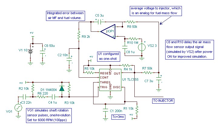
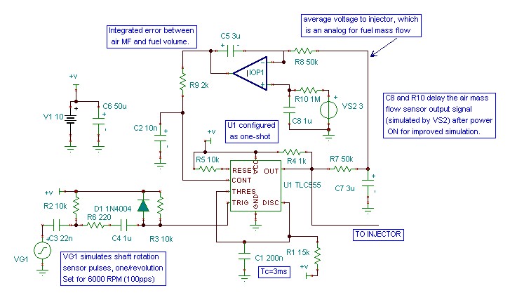
What you had lacked only a means to correlate airflow with fuel flow.
The addition of a resistor and a capacitor from the out put of the 555
to the inverting input of the mixture control op amp provided that,
allowing the circuit to compare MAF with Fuel flow. The schematic by
Vince Orton does just that and provides the basis for a working system.
Victor Roberts
Air is going in there all the time. Just some times more air goes in
than other
times. It all averages out over several revolutions. Same for the fuel
injected.
The mixture will average out in the intake manifold. . That is exactly
what Tracy
is doing now as the pulse width is controlled by the intake manifold
pressure
instead of a mass air flow sensor.
The engine runs fine. With an organ pipe system and a carb the same thing
happens. The air speeds up and slows down in the carb changing the
instantaneous
mixture. There is a huge cloud of mixture hanging in the air over the carb.
It has near zero effect on the BSFC.
We are not doing direct injection here.
The engine has rotating inertia. It is not going to speed up and slow down
from cycle to cycle.
Paul Lamar
--
The Rotary Engine NewsLetter. Powered by Linux.
ACRE NL web site.
http://www.rotaryeng.net
Youtube key word UTUBPLEASE
Copyright 1998-2009 All world wide rights reserved.