<snip
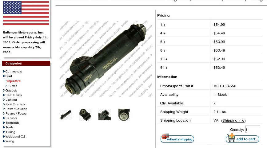
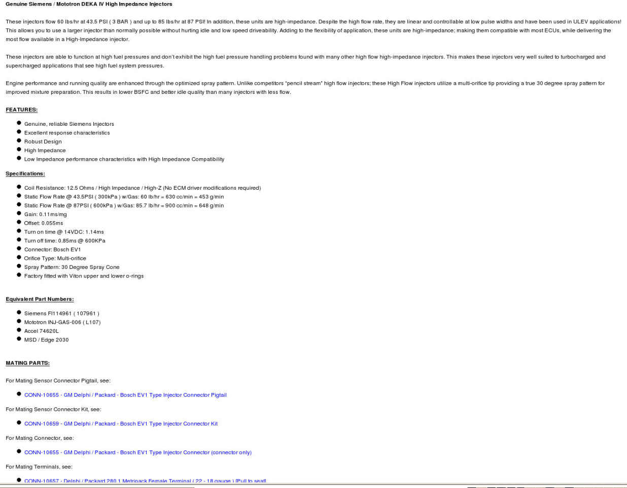
Based on the data from Paul's test of the MOTR-04556 injector and it's
spec sheet, using 8ms period free-running oscillator, the disparity in
fuel charge from one combustion cycle to another would be 2:3 if
operating at 6000rpm with a fuel flow rate of 80 lb/hr. The leanest
cycle would receive fuel for 3.2 milliseconds per rev and the richest
for 4.8 ms/rev. If the two injectors (per rotor) were driven by
separate
555 timers on opposite phases of the oscillator the disparities
would be
reduced, but would not disappear.
Victor Roberts
Why? I don't follow your reasoning? Are you referring to Paul Yaw's
data?
If so which chart?
Paul Lamar
Victor -
I wanted to respond to your observation above regarding fuel charge
disparity. I agree that there will be variations between combustion
cycles.
Please show some math, because I didn't follow how you arrived at the
2:3 ratio, or the 3.2ms vs. 4.8ms per rev. I'd like to understand how
to quantify the problem.
Using multiple injectors running at different phases is a good
solution to help "even out" the rich & lean spots. This essentially
increases injection frequency resolution by overlapping injection
events. Until I can quantify the problem, I cannot give an opinion on
what should be done.
Finally, keep in mind that this is a "wet runner" induction, and
therefore will have some mixing in the runners. This should help
"spread out" and "overlap" the rich and lean pulses of A/F ratios in
the runners. There will be turbulence and pressure pulses traversing
the runners along with other "randomizing" effects. To what degree
this occurs is conjecture at this point, and hopefully Paul's testing
will provide some answers.
Notes on various design effects:
- increasing injection freq increases injector open time % error
- reducing injection freq increases chamber A/F disparities
- increasing injector count w/phases reduces open time % error
*****
The MAF sensor is essentially telling us how much air is being
ingested. We need to inject a proportional amount of fuel based on
this voltage. We will do this by cycling injectors on and off at
varying duty cycles. This is the essence of the MAF/555 system.
If Paul goes with an Inject-Per-Revolution (IPR) scheme, then the
pulse width MUST vary proportionally with the INVERSE of the pulse
freq to maintain the correct duty cycle. In other words, as freq
(RPM) goes UP, pulse width goes DOWN to maintain the duty cycle.
Example with MAF calling for 40% fuel injector duty cycle (per second):
1500RPM = 25Hz = 40ms/rev; 40%=16ms; 25Hz * 16ms = 400ms
6000RPM = 100Hz = 10ms/rev; 40%=4ms; 100Hz * 4ms = 400ms
7500RPM = 125Hz = 8ms/rev; 40%=3.2ms; 125Hz * 3.2ms = 400ms
Failing to make this inverse proportion adjustment will result in
extreme fuel mixture errors and an engine that does not run. Also,
making this adjustment removes "simple" from "Simple 555 Timer Fuel
Injection".
For the record, I say let's go with the free-running oscillator
approach, like this link:
http://home.cogeco.ca/~rpaisley4/LM555.html#17
I like Victor's idea of phasing multiple injectors to minimize A/F
disparities, but I haven't found a circuit that maintains phase
between two 555 PWM generators. I'll wait to quantify the problem
before worrying about it.
-Vince Orton
Here is how I arrived at the cycle-to-cycle disparity.
Assume 200HP@ 6000 RPM (10 ms/rev)
Assume .40lb/hp/hr
Assume 2 rotors with 2 injectors each
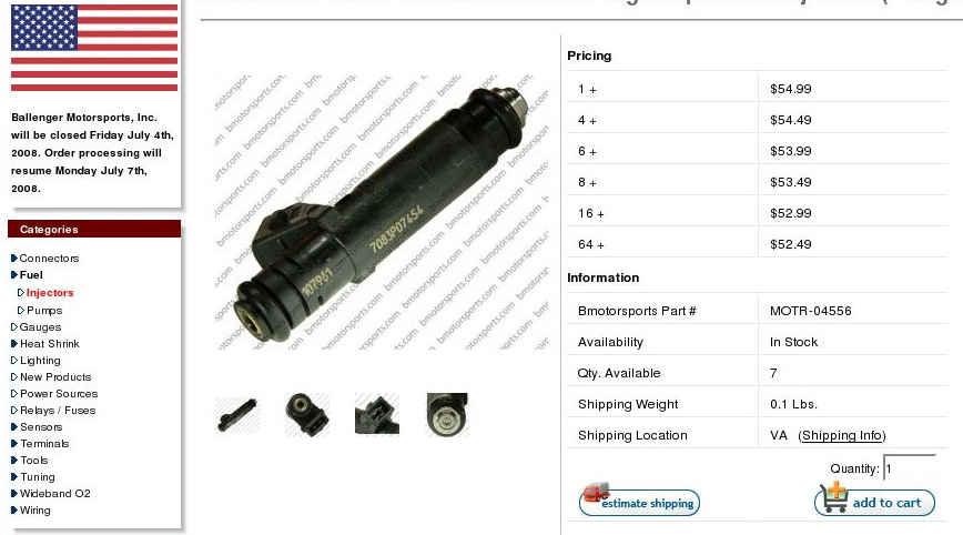
Assume MOTR-04556 injectors
Assume gal/hr x10.5 = cc/min
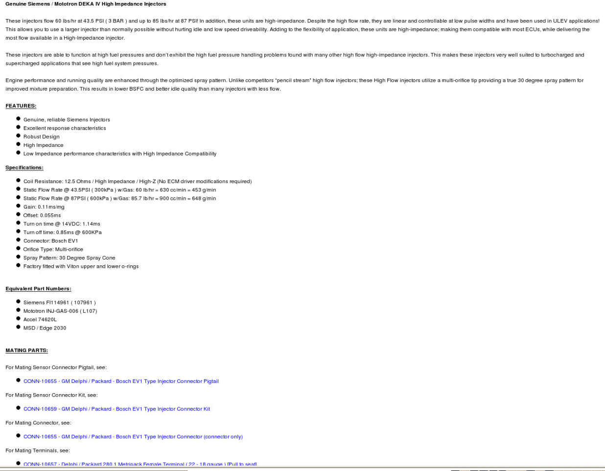
From the spec sheet: turn-on time 1.14ms, turn-off time .85 ms
200*.4 = 80lbs/hr = 840 cc/min divided by 2 rotors and 2 injectors/rotor
= 210cc/min
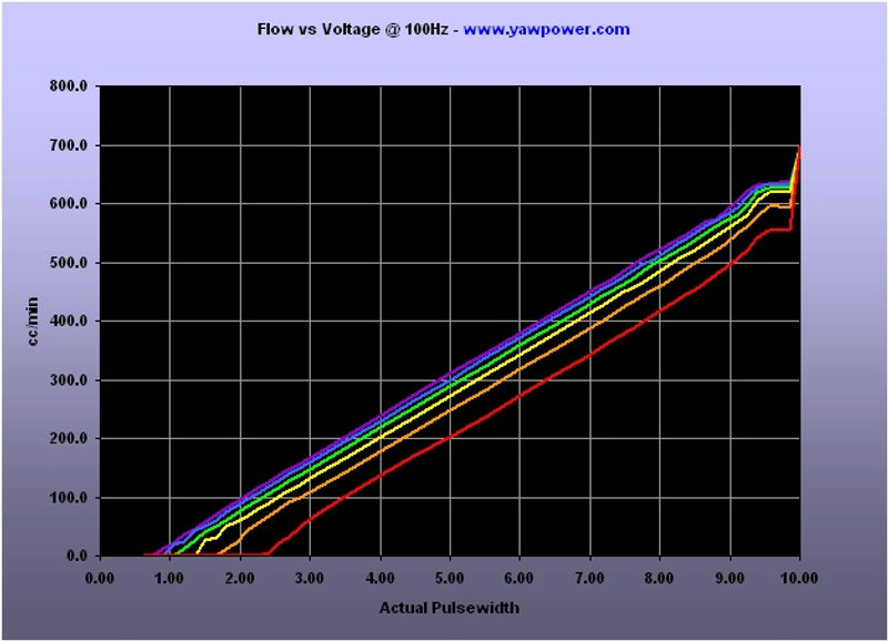
From Flow vs Voltage@100 hz a flow of 210cc/min requires a 3.5 second
pulsewidth. (I realize a 8ms period gives higher flow/minute)
A 3.5ms pulse nets a flow time of prox 3.2ms ( 3.5 ms + 1.14ms turn-on -
.85ms turn-off)
At 6000 a train of 3.2 ms pulses repeated at 8 ms intervals will be
partitioned into 10 ms intervals by the passing of the apex seal over
the intake port.
Assuming the first passing coincides with the arrival at the port of the
leading edge of a fuel flow pulse(mark this instant as time T), intake
will continue for 10 ms, ending 2 ms into the next fuel flow pulse,
resulting in 5.2 ms of fuel flow into rotor chamber 1. Beginning at
T+10ms,1.2 ms of flow remaining from the divided pulse will join 3.2 ms
of flow from the pulse beginning at T+16ms, (ending at T+19.2). The
charge into rotor chamber 2 is 4.4 ms of flow. The next fuel pulse
begins at T+24ms and ends at T+27.2ms, and is the only fuel charged into
rotor chamber 3, for 3.2 ms of fuel flow.
Someone smarter than me can figure out the distribution of the
percentage of times the leanest and richest events would occur, and the
percentage of combustions which would be about right.
Victor Roberts
My previous numbers of 4.8 and 3.2 were done by initiating parsing at
the application of electrical pulse to the injector and not at the
beginning of flow, which did not reveal the worst case disparity. My
apologies.
--
The Rotary Engine NewsLetter. Powered by Linux.
ACRE NL web site.
http://www.rotaryeng.net
Youtube key word UTUBPLEASE
Copyright 1998-2009 All world wide rights reserved.