Paul, throttle response of our peripheral port engines was very good on
the
ground and in the air, and at any point throughout the operating range.
No
discernible lag. No stumble with throttle advanced from idle slightly or
full throttle when on short final, etc. so made it very nice to fly. Idle
speed approx. 1000-1200 engine rpm. But we had the throttle shaft and
plates located inside the rotor housing. Although locating the throttles
in
the rotor housings is probably the optimum for response and idle speed,
it
involves a lot of work. Putting a slide or throttle-body with
plates/shafts
just outboard of port probably next best location.
Steve Beckham
As I recall Mazda placed the injectors close to the P-port on the Lemans
engine for throttle response reasons as it is very important when road
racing.
http://www.rotaryeng.net/Mazda_R26B_US.pdf
Also it might be a good idea to use a Megasquirt in this application.
The 555 system and Tracy system has no provision for rapid engine
acceleration.
We did discuss it at one time by putting a special switch on the throttle
knob to
temporarily enrich the mixture.
"Basically it is short stroke pancake air cylinder mounted on the slide
throttle
knob inside the cockpit with a small air hose connected to the back
side of the diaphragm in the Tillotson type carb. The increased air
pressure
will inject an extra shot of fuel and open the supply needle valve at the
same
time. When the knob is released the diaphragm spring will slowly restore
the diaphragm
and close the needle valve again.
Something like a 1 inch bore (2" OD) cylinder with a .5 inch stroke
or smaller should do the job. A spring inside the cylinder will restore
the
stroke after the knob is released. A one way valve on the intake port to
the cylinder
will fill the cylinder with air."
Paul Lamar
Paul and group,
Every racing and street EFI that I have encountered has a throttle
position sensor. The rapid opening of the throttle at low RPM should
automatically
enrichen the mixture. Since the injection is a demand system based on RPM
of the pump, and the stroke or the time of opening the injector, the
throttle response should be better than any carb system. Airflow
performance type
systems use the differential between the servo pressure and the inlet
pressure to do the same thing. Hilborn style systems connect a valve
directly to
the throttle shaft that does the same thing. (I know Paul knows this
already but it should be built into any EFI system.) The basics of fuel
injection is so intuitive that it is supprising that the carburetor came
first.
Even a system without a throttle position sensor should have programing
ability to richen using the map sensor. Older alpha-n systems used only a
TPS and
RPM with a programmed fuel map. We are talking about making a injector
pump like used in a carb. This shouldn't be needed in a EFI. Just my
$0.02.
Bill Jepson
--------------------------------------------------------------------------------
Thanks Bill. Your review reminded me that I should have included in the
original note that our system reviewed was not electronic.
We started out with an original design system that used some Hillborn
components such as pump and valves. On the second generation SuperLight
engine in the early 1990's, we wanted to use a proven, available system, so
adapted Don Rivera's complete Airflow Performance system developed from when
he worked for Bendix. But before our application, Don had already
successfully adapted it to Mazda race engines built and campaigned so well
in the factory-backed rotary cars built and driven by Roger Mandeville and
his team. Don also worked with Jim Mederer in his work using the Airflow
Performance system. Roger used Don's system up until the later refinement
of the British and similar electronic race car units were sorted and
available.
For the conversion Mazda engine intended for production in the late 1990's,
we tailored Don's system to our engine configurations by making our own
little venturi for optimum packaging in tight cowlings, with the verturi
providing the inlet to the intake plenum to provide signal to Don's
servo/controller. We machined a backside billet cover which sealed the
servo diapraham and aso had incorporated holes for bolting to the engine via
existing Mazda provision in the housings. The servo was mounted on the
other side of the engine opposite from the plenum, so we could interconnect
the servo with the throttle and throttle shaft arms with a short
heim-jointed arm. So when you moved the throttle lever it simulataneously
moved the servo arm. In standard form, Don's unit for reciprocating
aircraft and race cars comes with verturi and servo/controller all cast in
the same piece.
On the newsletter I've seen some discussion of driving a fuel pump with a
Gilmer/tooth belt. Originally we started out with the Hillborn-based system
where the fuel pump was driven by a Gilmer belt. When we started dyno
testing engines, we always did so with the propeller reduction gear
installed--water brake dyno to start and later when we built the dyno to for
using a club/propeller. The engine had no flywheel, just a very light unit
to hold the starter ring gear. Of course the combined torsional factors are
significantly different than in a car. In early testing, before we got our
act together and understood and addressed the torsional and other issues, at
certain speeds on dyno pulls, the Gilmer belt would blur and jump off the
Hilborn pump pulley; skipping teeth and (sometimes) reattaching when the rpm
dropped with related misfire. Something to think about when considering
different fuel injection pump/engine configurations. These misfires could
combine with other factors to destroy gear teeth and this included rotor
gears/stationary gears.
This early engine had a plenum and throttle plates located way up at the
front of the intake runners which ranged from 18"-2 ft long (our target rpm
was 5-5,500 rpm). Because the throttle plates were so far upstream, the idle
and throttle response was lousy but made 200 h.p. with dual side port
aluminum housings @ 7,000 rpm. We then switched to a peripheral port system
that experimented with various port shapes, port timing and runner dia and
length. These engine outputs ranged were engineered and performed well at
lower rated rpm: 180+ hp @ 5500 and 200 @ 5900 rpm; more at higher rpm and
limited in flight to 7,000 rpm for races.
In conclusion, it seems natural for folks working on electronic systems to
turn their noses down on a mechanical, constant flow systems such as Don's
and the Bendix and Continental, as crude and simple. They are indeed
simple, but they are not crude, and the result of over half a century of
development and use. Obviously an electronic system has more sophistication
in design and potential for some degree of performance increase at cruise
and altitude. In the use of homogenous-charge rotary engines in aircraft
where we operate most of the time at a relatively fixed power setting
(cruise), there are important basic questions for each builder. Are the
relatively small gains of electronic injection, at this stage of development
for home-grown efforts, more than offset by installation and tuning
complexity, and lack of development and reliability?
We looked long and hard at electronic systems and used them on Chevy, Ford
and Nissan engines built in the shop for IMSA and other applications. There
were the inevitable major development and teething issues as the systems
were developed and tested. We see that same cycle today with homebuilt
aircraft. It goes without saying that, unlike a race car which can be
pulled off course when it fails, the airplane driver has no such luxury when
the damned thing fails. Despite this admonition, we worked on various
electonic system designs for our rotary aircraft engines over an eight year
period up until late 1997, with the folks who developed the race car
systems. But for proven performance, flight safety, ease of installation
and operation, we found nothing surpassed Don's Airflow Performance system.
Even today, over 10 years later, using that critera, it can be argued none
of the electronic systems available to homebuilders today can presently
measure up to that combined critera at this stage of development. Don's
system is no doubt more expensive than a home grown electronic system. But
we found it totally without fault--nuts on reliable, easy to install,
responsive, proven and simple, and he works with you to tailor and tune it
to each application; including in the airplane. A lot to be said when the
goal is to get the airplane flying, perform well, often and reliably...and
especially when you are not an electronics engineer experienced with
engines. Apologize for the verbosity.
Steve Beckham
Steve, if you ever do a book on the history of Power Sport I have saved all your
messages.
Paul Lamar
Craig Taylor here;
After reading Steve Beckham's interesting letter above, I have a few thoughts.
For aircraft rotary applications, the timing of the fuel squirt from an individual injector
shouldn't be critical. After all, the air flow into the chamber does vary over time but it never
actually stops. Therefore I can't help but wonder if a continuous injection system based on RPM and
MAF wouldn't be close to optimum. It should also be easier to implement a "limp home" mode than
with an electric pulse injector. Possibly a transfer switch and a control knob to hand vary the
fuel flow would suffice. It could be purely passive and work as long as there was fuel pressure.
An electrically variable valve coupled to an inline fuel flow meter would allow well controlled
fuel flow. Varying the flow proportional to RPM would give a first approximation of a constant
air/fuel ratio. Adding MAF as the modifier of the RPM signal would give a tighter control, of
course. Finally, using an exhaust oxygen sensor would allow constant speed, level flight tweaking
to maximize economy. Maybe. The original intent of the oxygen sensor was, I believe, to minimize
HC emissions from auto engines. So it may not be the best indicator of optimum mileage for an airplane.
Just some thoughts. A rotary engine for aircraft use is just a completely different beast than a
piston automobile engine. ESPECIALLY when it comes to sub-1000 RPM idle. Why spend lots of time
and money optimizing low speed and/or low load operating conditions?
Craig Taylor
Nobody idles them much less than 2000 RPM as the gear box will not tolerate it.
The prop is only going 700 RPM. The same as an air cooled aircraft engine.
Klause built a limp home mode fuel system consisting of a gravity feed header tank
and a pet cock. Almost exactly like the Wright brothers used. The feed tube was merely
plumbed to a hole in the intake manifold. Once you got it stabilized you kept that
throttle opening until you were ready to dead stick it in. You could use a hand pump
to keep the header tanks full.
BTW every body should practice
slips. Highly useful for getting it in the first time :)
Paul Lamar
Along those same thoughts, here is a nice little flow sensor designed for gasoline and reasonably
priced. Well, $250 seems reasonable to me compared to other instrument I have seen. Se the
attached PDF.
Tom Craig
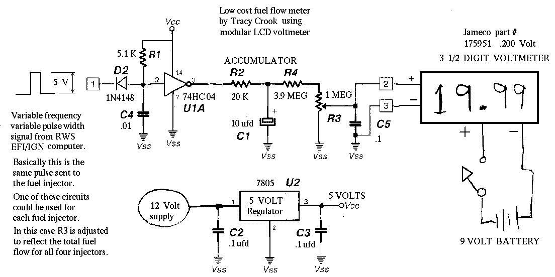
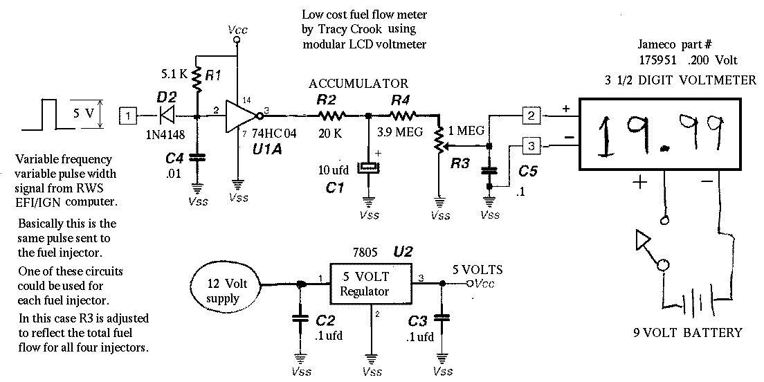
Here is a cheaper way to do it if you are using PWM EFI.
Paul Lamar
--
The Rotary Engine NewsLetter. Powered by Linux.
ACRE NL web site.
http://www.rotaryeng.net
Youtube key word UTUBPLEASE
Copyright 1998-2009 All world wide rights reserved.