I'm using Bruce Turrentine's DVD to overhaul a 20B. On the rear of the
engine there is a counter weight under the flywheel that didn't appear on
the 13B in Bruce's video. Anyone familiar with this and know how to
remove
this counter weight?
Jay
I think you mean the flex plate for the auto transmission.
The 20B is very similar to the 3rd gen RX7 engines. 1993 to
2003.
For that you will need a gear puller and a way of locking the E-shaft
with a special plate.
Go to this location:
http://foxed.ca/foxed/index.php?page=rx7manual
and download the chapter C engine.pdf shop manual:
http://foxed.ca/rx7manual/manuals/1993FSM/
Here is an excerpt.
Paul Lamar
For the 13B, you can use the six bolts / bolt holes connecting the
flexplate/driveplate to the counterweight.
The 10?mm CW bolt thread pitch is common to many RX7 bolts. You may
want a few that are slightly longer.
- Lock the flex/driveplate
- Loosen the 54mm locknut but leave it on a few threads (so it does not
fly off and crush your toes, even more important with a flywheel). A 6'
breaker bar extension helps.
Without the stock puller:
- I use pieces of scrap angle iron between the rear iron and the CW to
push against with bolts in the CW bolt holes. (angle iron placed to
distribute the load)
- Turn the bolts 1/4 turn each in the usual star pattern and it will pop
right off.
Cheers
Cary
Cary,
What about the front end? I am having a bear of a time getting the
pulley bolt to budge. I made a device that was similar to the Mazda
tool to lock the flywheel from turning and braced the engine with a
stout U-beam, sprayed WD-40 on the bolt and used a four foot pipe over
the breaker bar. Still no joy. Guess I have to try a longer pipe or
gain a few more pounds huh?
Doug in Japan.
That puller did the trick. Thanks a lot.
Now I'm down to the center housing and the housing on either side of it.
But
there is little or no play (engine length wise) in the E shaft. Thus I
can't
get either of the remaining housings on the end up and over the E shaft.
Bruce's DVD shows the shaft moving up and down at least an inch or more. I
can hardly get mine to move at all.
Any ideas?
Jay
Do you have the front cover off and the thrust bearing removed?
Paul Lamar
Jay,
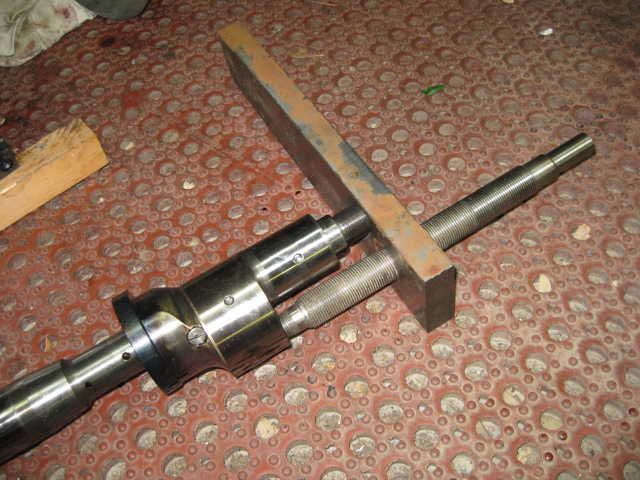
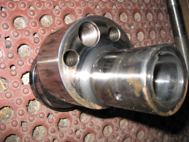
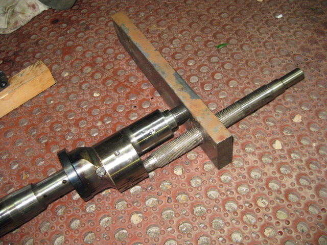
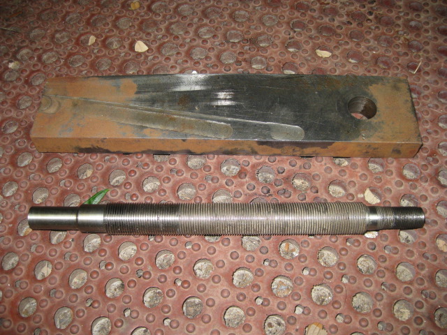
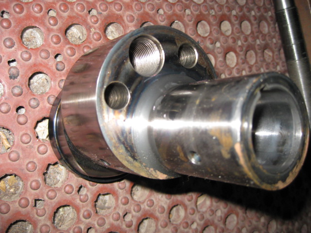
The 20B utilizes a split shaft. You're going to have to separate it in
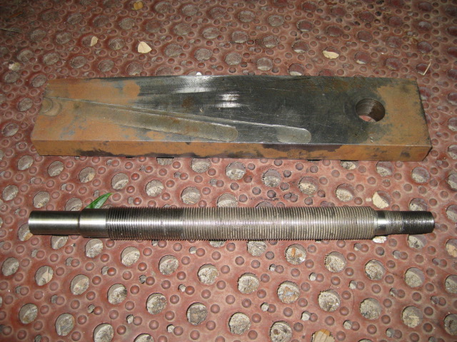
order to disassemble the engine. Bob Darrah built a splitter tool from a
threaded shaft and a 1" thick bar of steel. The threaded shaft will need to
match the threads in the #1 lobe on the crank, 18mm if I recall correctly.
Thread the shaft into the lobe, slide the 1" bar over the other end of the
threaded shaft until it fits snug against the nose of the eccentric, put a
nut on the threaded shaft to tighten it all down. You may want to use a
soft aluminum or brass spacer so you don't bugger up the end of the
eccentric. Tighten the nut until it cocks the 1" bar a little, then tap the
other end of the bar with a hammer and it should come right apart, at least
that's how it has worked for me twice. Now you can finish disassembling the
engine. Remember the sequence for when you are ready to re-assemble it.
Mark S.
--
The Rotary Engine NewsLetter. Powered by Linux.
ACRE NL web site.
http://www.rotaryeng.net
Youtube key word UTUBPLEASE
Copyright 1998-2009 All world wide rights reserved.