Paul, I received 2 copies of Contact! #89 from Mr. Morgan. Just wondering if
you received anything, I can mail you a copy, and or scan some pages.
C. Smith
Not yet. I'll check the mail tomorrow.
I got the article and the Installation Handbook from Mr. Morgan. Thank you Mr. Morgan.
Very interesting idea. They used my annular clutch throw out slave cylinder invention
invented in 1971 now widely used on most auto transmission cars to change the pitch of
the blades. There is a serious error in the dwg of the device that will confuse most
people. I'll have to redraw it to clarify but it has to do with the allowable travel of
the annular slave cylinder. Here is a modified sketch.
They use a PWM electric motor to provide the oil pressure to change the prop blade
pitch. It is not necessary to do this with a leak free system. You could mount a long
travel, small diameter cylinder behind the instrument panel and change the pitch merely
by pushing in the piston rod with a knob on it. It would look just like the pitch
control on a C182. There is a European designed variable pitch prop that does it this
way. Super simple. Just like a clutch master cylinder in a car. That would save a lot of
money. However you would not have the automatically controlled constant speed feature.
That requires the PWM electric motor or a conventional prop govenor.
Paul Lamar
Hi Paul,
A couple of notes, I am not familiar with the device you referred to as being invented
in 1971. This evolved from a rack and gear system. As to the long cylinder behind the
instrument panel, Been done. Two issues. #1, you don't have enough strength to adjust
the system during operation, and without a HUGE mechanical advantage you don't have the
precision available. The blade's travel is very little during operation.
Larry
I got the 6,478,542 patent number from the hand book you sent me Larry. It is on the
second page. It was patented in 2002. Yes I know you don't use the rack and pinion to
change the pitch of the blades. You use a very common and almost standard spool to do
that job. The blade travel force depends on the axis of rotation position relative to
the blade cord so I don't have a blade drawing to go on. For example if the blade
rotation axis is on the 1/4 cord point of the blade the force to rotate the blade will
be a minimum. The force and travel is also a function of the distance of the pin from
the axis. Again I don't have a dwg to determine that.
The force available from the control cylinder mounted behind the instrument panel
depends on the diameter of the piston used. My guess is 100 psi is needed to change the
pitch on most hydraulic props. If the average person can push 20 pounds the area of the
control piston would have to be .2 square inches. .2 square inches / 3.1416 = the
radius squared or .0638 inches. The square root of which is 0.252. Therefor the control
piston would only need to be about .5 inches in diameter. The travel or distance needed
has been discussed above. The mechanical advantage is five to one so a five inch change
in the master cylinder or control knob will move the spool one inch which should be more
than enough to change the pitch throughout the entire range.
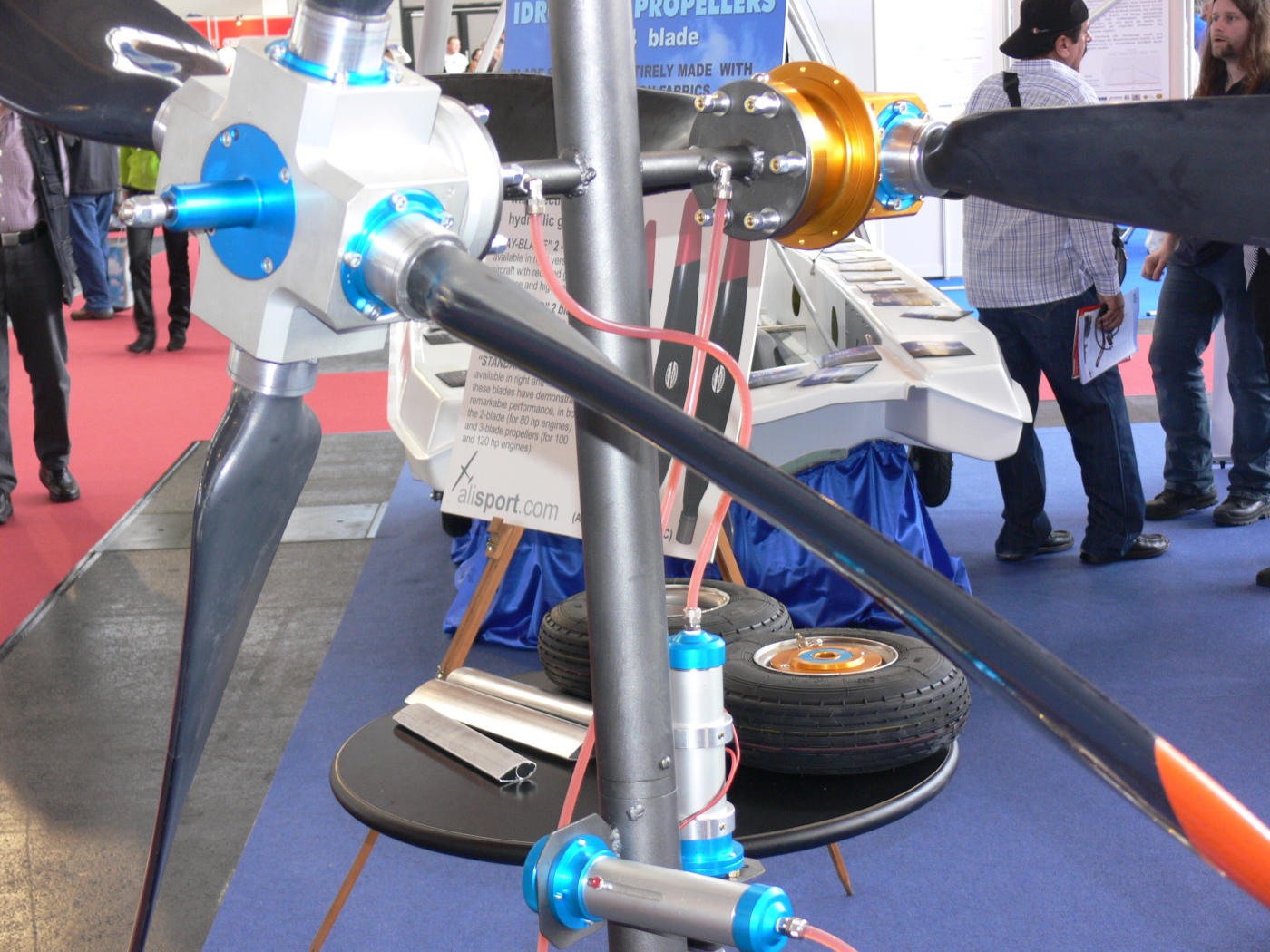
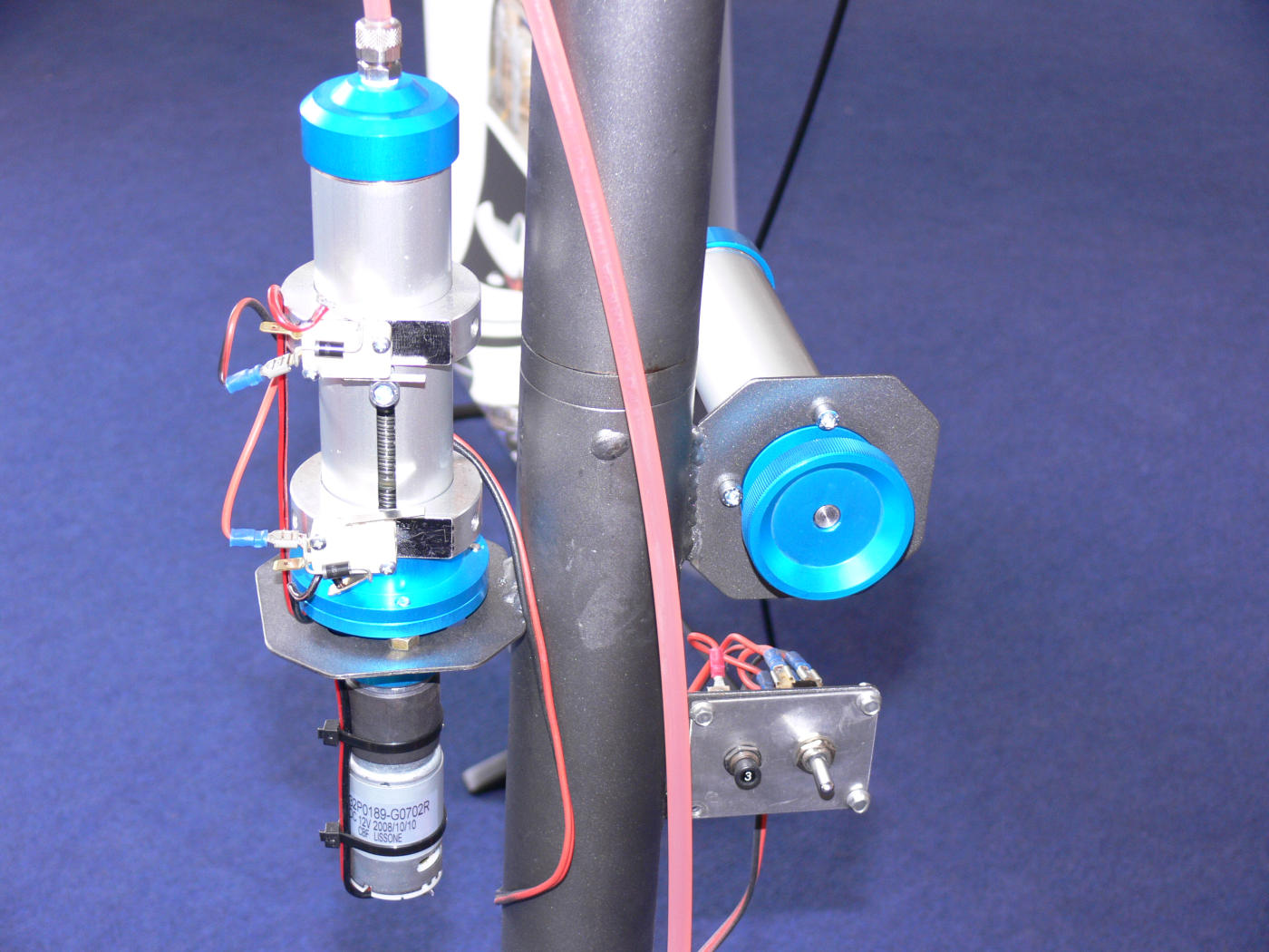
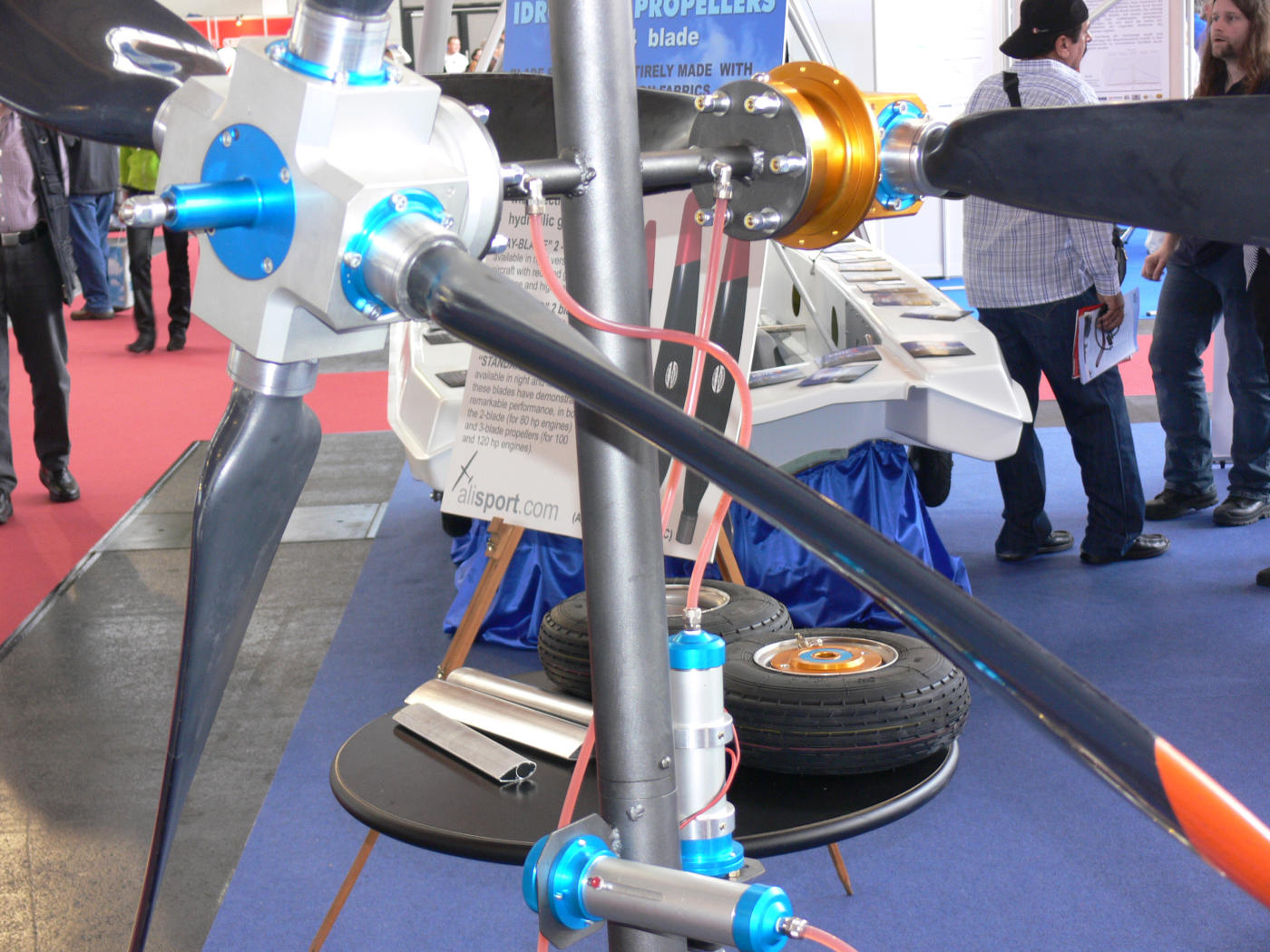
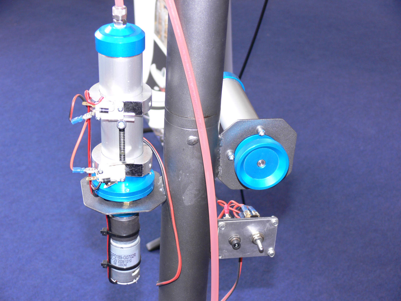
Here are some pictures of the European prop that uses this method of control.
BTW What is the correct second patent number?
Paul Lamar
--
The Rotary Engine NewsLetter. Powered by Linux.
ACRE NL web site.
http://www.rotaryeng.net
Youtube key word UTUBPLEASE
Copyright 1998-2009 All world wide rights reserved.