Paul
The temperature compensation was only an idea.
Not a good one as it turns out.
Ah ha, just, re-read your comment.
Obvious---the pot alters the mixture proportionally to 555 increasing or
decreasing the pulse width across the whole range.
The temp sensor is another input, hence the need for computamebobs,
that we
don't want.
Here's another idea (so don't shoot me if no good)
Could the MAP output be also used to drive a PFM for the fuel pump?
Someone was working on that a while back.
Clive.
Yes I think that could be made to work. However I, like Dave Leonard
prefer
a
full return system for several reasons. One of which it is known to work.
-------------------------------------------------------------------------
I have given this a bit more thought since Clive mentioned it again.
One 555 with input from a crank angle sensor and manifold pressure might
work.
It looks like one of the cheapest fuel injection systems of all as you
need
the fuel pump anyway. The fuel injected is both pulse width modulated by
manifold pressure and proportional to engine RPM by pulse rate. It is the
product of RPM and manifold pressure. Easy to check on the bench as
all you
need is a hand vacuum pump to simulate manifold pressure and a pulse
generator to simulate the crank angle sensor.
One problems is controlling the power supply voltage to the fuel pump.
The
voltage regulator in most alternators maintain the supply at 13.9
volts more
or less which may be sufficient.
The simple mechanical passive injectors themselves are available in a
wide
variety from Kinsler.
http://www.kinsler.com/page--Home-Page--13.html
------------------------------------------------------
More info on the size of the injector orifice to try. The rotary has one
large advantage here as one injector in effect services two cylinders
in an
equivalent 4 cylinder engine. This means they can be twice the area.
Paul Lamar
Hi Paul
That sure would be a simple system.
555 PWM RPM/MAP controlled fuel pump constant flow injectors.
No return plumbing.
Fully redundant system:-
2 x 555 controllers
2 x pumps
2x leaning rheostats
1 x Control divider
1 x on/off/on switch.
As many or few injectors as you want. (If you want to be really cheap a
spray tube would probably work upstream)
I don't think the 13.9 volts is a problem as Kinsler market the Weldon
"Dial-A-Flow" PWM fuel pump controller that does the same job without the
RPM controlled element, so no good in this application, its $400 (ouch).
It can be found on page 130 of the Kinsler 2008 catalogue link provided
below. They list pages 124-129 for suitable pumps to use and it's a big
list.
RPM and load sensing, so suitable for turbos and wobbly props???
Clive
There is no reason to expect the fuel pump output volume would have a
linear relationship with the input voltage. You will need to detect the
pump output and compare it to the integrated 555 output to drive the
pump. If the pump is a positive displacement type you can use the pump
RPM as a signal for comparison, otherwise you need a flowmeter turbine
or pressure sensor.
Victor Roberts
You have a point there. I'll find out when I bench test it.
The one I have is positive displacement.
---------------------------------------------
Here is some data from Kinsler on the subject.
They have the output pressure constant at 40 psi which will not happen in the
real world however it is not that far off linear in this range. It might work.
Paul Lamar
All,
You don't need a computer to use a temperature compensator. Many temp
sensors are available that are a variable (with temperature) resistor. Any
competent analog circuit designer can use a variable resistor to change the
"gain" of the pulse width control voltage.
Another approach is to use a trick called a "rate multiplier" to allow a
variable gain for the PWM control signal. This allows a voltage or current
(rather than a variable resistor) to be the multiplier control signal.
By the way, the input to the 555 usually used to control the pulse width,
using the 555 CONTROL input, will NOT be linear with voltage. That's because
the voltage on the timing capacitor is NOT a linear ramp; it's an
exponential. Actually, it's the center cut out of an exponential RC charging
curve going from 1/3 final voltage to 2/3 final voltage. You could make the
pulse width linear by using a constant current source to charge the capacitor
instead of a resistor connected to the positive supply voltage. That's a bit
more complicated but not too bad. More opamps required, but they're cheap ;-)
Craig Taylor
Have you tried the CMOS version of the 555? TLC 555? I was stunned to find
out how linear it was. I gave up on the old version for that reasons.
Paul Lamar
Craig here,
The only difference between the older, bipolar 555 and the newer CMOS version
is the lower power consumption and higher input impedance of the CMOS
device. Very nice because it allows easier interfacing with external inputs
to the 555.
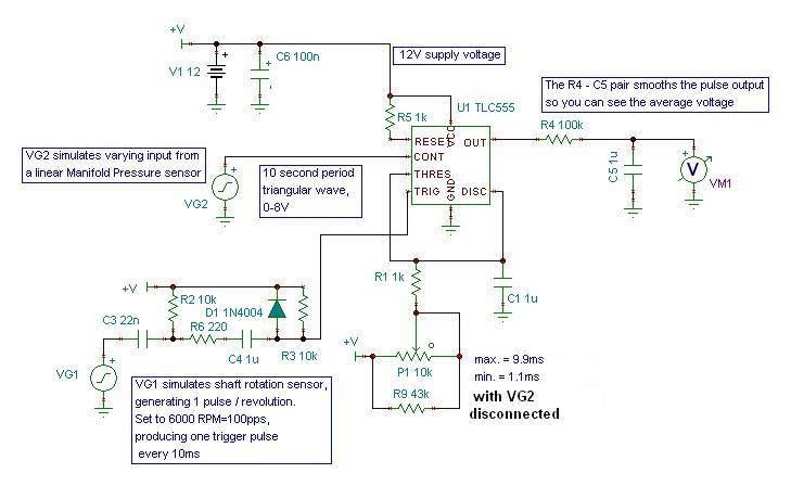
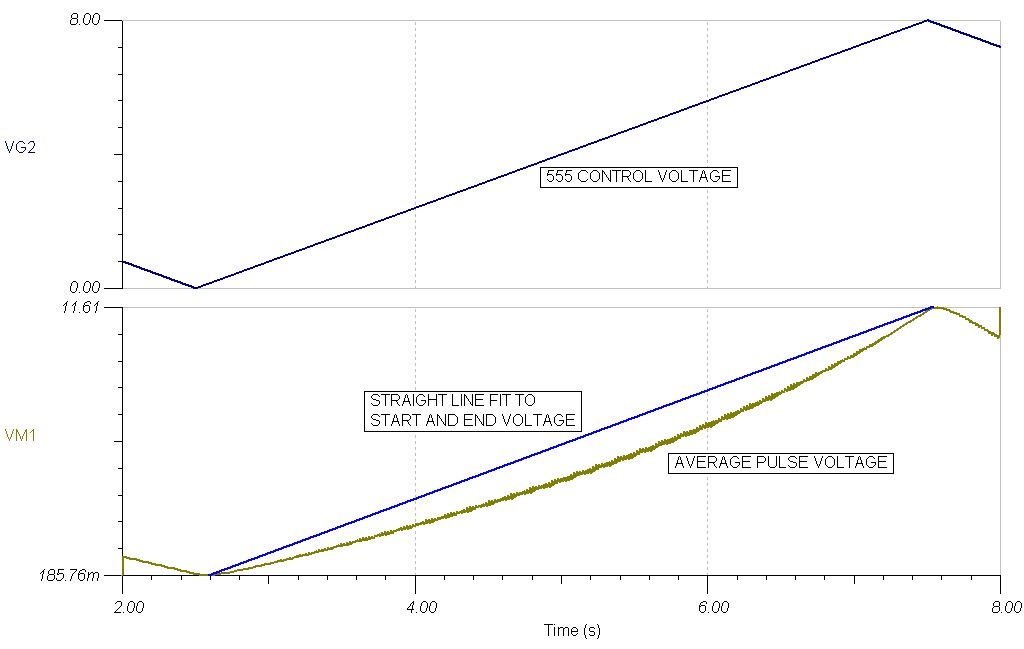
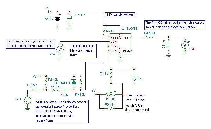
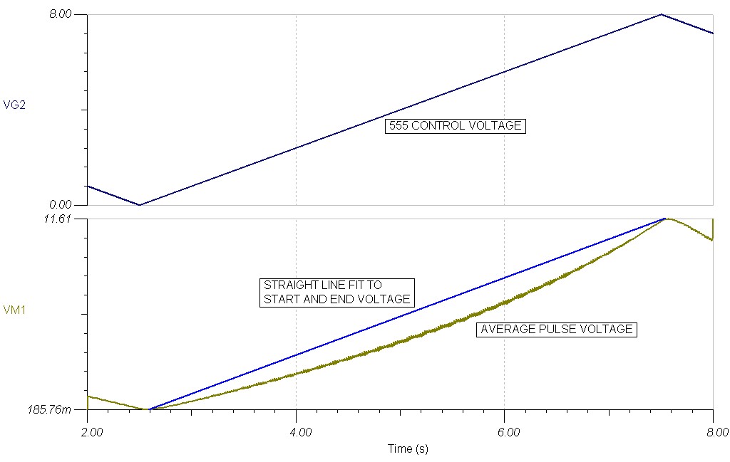
I ran a simulation of the CMOS 555 using SPICE with good models. For a
linear CONTROL voltage the pulse width changed in a non-linear fashion. I am
going to try and attach a diagram of the output pulse width vs input control
voltage to show the effect. I havn't attached any jpg files before so I
really don't know the results.
Craig Taylor
The jpgs came across fine. You are using a 12 volt supply while we are
using a 5 volt supply. Take out R4 and C5 and run the the simulation again.
One needs to see the pulse width exactly and not the average voltage out.
It is the pulse width that is of interest.
Given those differences it is still not all that bad. Also perhaps Spice is
a flawed simulation. Computer models are frequently wrong. They are subject
to the foibles of the programmer. Look at Global Warming predictions for a
good example. Garbage in garbage out. As far as I can measure the TI TLC 555
is linear to sufficient use for a fuel injection system. There are no smog
rules here and the rotary will run from a 10:1 to a 20:1 mixture ranges. That
is all we care about as we manually lean the engine for cruise.
Happy Thanks Giving. I just stuffed myself :(
Paul Lamar
--
The Rotary Engine NewsLetter. Powered by Linux.
ACRE NL web site.
http://www.rotaryeng.net
Youtube key word UTUBPLEASE
Copyright 1998-2009 All world wide rights reserved.