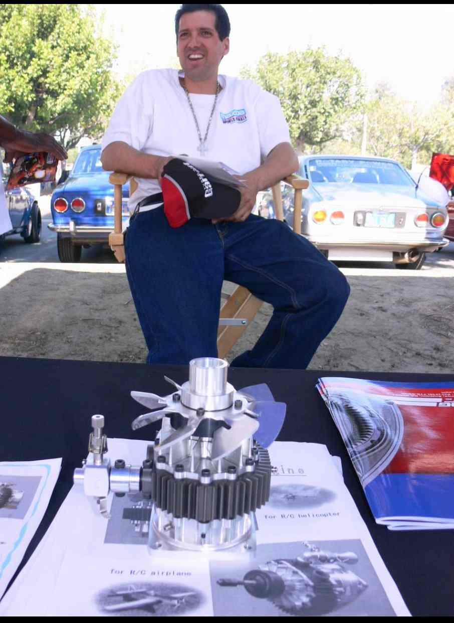
That is interesting. I have been thinking along the
same lines
recently. I'm building a 14" disc prototype. I
guess my input would be
to consider water injection as well. I've seen posted
the thought that
spacers on the periphery don't degrade efficiency. If
you used wafer
thin ferrite magnets you might be able to use the turbine
as your
alternator. I'd be very interested in seeing any
formulae you may have
found in your research to calculate efficiencies, etc.
Decker, Michael
If you'r suggesting the magnets are also exposed to the exaust stream,
it's a non starter. The magnets subjected to that high a temp. would
surely reach the Curie pt where the magnetic properties go to zero.
Robert
Michael,
I attached a file for you. Be warned. I don't think this guy has even
built a unit yet. There is some accurate historical data there on sizes
verses output and some brief sentences of clarity but you have to filter
out a lot of other BS, speculation and rants. Pretty much what you find
when sifting through the Internet. I am still waiting from responses
from people who have actually made a turbine to run off car exhaust
gases.
Do you have Tesla's patent? You can find it on the Tesla group's
website in Milwaukee..
14" is quite large to fly with and it will be heavy. More important it
will have to kept slow, probably under 3,000 rpms as it becomes a large
flywheel and can store a lot of inertia. The G forces placed on the
discs is in relationship to their mass and rpms. Heating the alloys
will weaken it even more. There are other issues as listed below.
Some challenges for using any turbine on the aircraft bound rotary are:
Location, exhaust piping, loss of heat and energy in the piping and
turbine housing, means of bypassing the turbine, vibration isolation,
isolating the hot components from other engine components while safely
exhausting the heat from the cowl. Obviously you don't want hot things
near the water hoses, electrical wires, fuel line nor near any
alternator or magnets. Electrical efficiency goes down as the heat goes
up.
With these points in mind it is no wonder that turbine installations
tend to be on short well designed manifolds with little gas flow
resistance. The heat signature is keep small and it is relatively easy
to shield and exhaust.
With a Tesla turbine, nozzle design is important. I'm still clueless as
to why though. We do have an exhaust port that is about 2" in
diameter. Do we cone it down to inch, fan it out and wrap it around.
Coning it down will increase back pressure and concentrate the flow on
lets say ten plates. Leaving it wide will let it hit twenty plate.
Narrow is good and lighter and allows flow to all come out of one side
only.We don't know if the resulting back pressure will harm the
engine performance. So I have to measure the necked down nozzle within
the Mazda turbocharger to get an idea of what it can handle. A boosted
p-port will be more robust no doubt.
Placement: If the unit is on the hot side of the engine and is to spin
the same way as the engine is rotating, the bottom of the Tesla turbines
will have to be near or slightly above the exhaust ports. Clearing the
intake pipe become a limiting factor in diameter size. Farther from the
engine increases allowable diameter but also increases cowl size and
flat plate drag as well as increasing thermal losses, in the piping,
increases pulley mounting flange weight and increases bending moment on
the exhaust manifold.
Output: The shortest shaft length will be in direction of the PSRU but
this demands the redesign of the PSRU sun shaft and torque absorber.
Ditto pulley mount designs. Add to this is the fact that the turbine
position will change a little when the exhaust manifold becomes hot.
The design has to allow for this movement or something is going to
crack. There are unused bolts on the side housing that can be used to
mount a angled plate with a bearing or two to handle the side force
exerted by the multi-v belt. I chose the PSRU side because the sun
shaft is supported by bearings on the engine side as well as the PSRU
side. No overhang which would be an issue to resolve on the accessories
end side. I am planning a large six inch or more multi V pulley on a
keyed sun shaft that encapsulates the torque absorber bolted to the
counter-weight.
Turbine challenge. Telsa turbines work off of boundary layer adhesion
and are similar to the adhesion between discs in automatic
transmissions. Instead of oil or steam this one is running on fluid
air. How to calculate their maximum hp rpm? Max torque is not at zero
rpms. like other turbines. Minimal torque is not at maximum rpms
either.When forced to do work some slippage must occur if it
overworked. This is a good thing. The unit can be closed coupled to the
engine because of this perhaps an sprague clutch could be used in case
it needs to be disengaged. The pulley ratio would be set to obtain
maximum turbine efficiency at say 6,000 cruise rpm.
I believe Tesla's first unit of six plates total, had an internal width
of less than one inch. Disc dia. was 5.75" and it made about 30HP.
Assuming his air power source was stronger than exhaust power and we
will use more discs I would be happy to get 15 HPs from each unit.
Paul what is the wasted power in kinetic energy coming out of the 13B at
200 hp setting. 80 hp?
I would also love to know what the gas pressure exiting the exhaust port
on a rotary is. Velocity is probably near the speed of sound.
Doug in Japan
What is that file that you attached Doug? It had no file extension to
identify it.
I think the kinetic energy is higher than 8O HP in a 250 HP p-port
engine.
The static pressure is only a few psi. What you are interested in is the
dynamic pressure. Lets say the exhaust speed is just subsonic at 600
MPH. Dynamic pressure would be 936 pounds per square foot or 6.5 pounds
per square inch.
Lets say we have ten small wings one inch square area with a lift
coefficient of one. Lets also say these wings are on a radius of 1.5
inches. The torque would then be 97.5 inch pounds or 8 foot pounds at
say 50,000 RPM. Turbine HP might then be close to 77 HP. Close to your
estimated 80 HP. Peak HP would occur around 70,000 RPM so the HP might
be as high as 90 or 100 HP.
Here is an update on the heat balance of the rotary engine.
Fully 154% of output power is wasted in the exhaust. In other words
almost 384 HP is wasted in the exhaust of a 250 HP rotary engine. If we
can recover only 25% of that it would be 96 recovered HP. With a few
years of development we might get up to 35% or 134 recovered HP. The
BSFC would drop from .47 to close .3. No gasoline burning internal
combustion engine has ever been built to reach that low of a BSFC. That
includes the CW R3350TC and the Napier Nomad TC diesel.
Paul Lamar
Thanks for the added comments. I'm building the 14" because I want to
try one out and 14" turned out to be the best size to maximize surface
area/$. I've got all my parts now and I'll be putting it together
either this week or the last week of December. This is a test bed to
try to ballpark the efficiency curve. I've not had much luck finding
equations for that so I'm pretty much designing off of fluid dynamics.
I'll report what I find.
Decker, Michael
Hey guys if the Tesla turbine is 14 inches in diameter and 2 inch wide
and 30% air it will weigh 55 pounds. Not something one would want to
put in an airplane.
Paul Lamar
I would for 55 HP and a 0.1 improvement in BSFC.
Fred O.
Thats is just the turbine. It doesn't include all the other stuff you need for a
turbo compound such as a gear box and compressor.
If you could do the same thing for 20 pounds which would you choose? :)
A TO4 turbo charger weighs 16 pounds with turbine and compressor.
Paul Lamar
Tesla turbines are something I have been puzzling over for some time. I
remember a picture of a 10" dia 3 disk turbine putting out 125hp.
http://www.teslaengine.org/main.html has a lot of info, does anyone have a
membership? (on my wishlist) Would it be practical to mount a (about 14"dia)
turbine inline and drive the output via another planetary reduction set?
Since the pressure is low is there some material available for a gasket to use
in a SS or Inconel Wiggins joint to compensate for heat expansion? The
lightweight PSRU idea combined with mostly sheet metal construction may be an
acceptable trade off for an additional 80+? hp and corresponding reduction in BSCF.
Dan F
Paul,
Some more thoughts on turbo compounding. Reading the NACA. report No 822
again it was revealed the blowdown turbines were calculated to be 85%
efficient. Total reduction in BSFC at sealevel was 9% and 21% at
30,000 Mentioned throughout the text are the words "gear turbine and
supercharger." In other words, both objects were geared to the engine
shaft and that for calculation purposes it should be assumed they are
gear to the same shaft.
The first paragraph of the INTRODUCTION states that "The use of an
exhaust gas turbine to drive a supercharger at high altitudes is an
effective method of maintaining sea level engine power at altitude.
Talking about a turbocharger here. Next line. "Analysis has shown
however that the waste energy of the exhaust gases is recovered more
effectively by maintaining an engine exhaust pressure higher than the
minimum required for turbosupercharging.
Next paragraph.
"The purpose of the analysis reported is to determine the improvement in
net brake specific fuel consumption that can be obtained if an engine is
equipped with a geared turbine and [geared] supercharger as compared
with the engine using a standard turbosupercharger.
Note this means it is inherently more efficient to use a supercharger to
boost the engine to higher exhaust pressures than required for to run a
turbocharger. Hence all exhaust energy at a higher potential level
goes through a highly efficient blowdown turbine.
This is a important concept.
Yes the rotary wankel has a more powerful exhaust then the old [radial]
piston engines but the operating efficiencies of centfrigical turbines
found in mass produced turbochargers are only about 50%. Operating
efficiency of the compressor are about 70%. Total power extraction
efficiency therefore is about 35%. Actually lower if the an
intercooler has to be used. I have heard about 1/3 of exhaust energy
extraction numerous times so this estimate is probably correct.
As you and others have mentioned many times the rotary has exhaust energy
in excess of the 30 or so hp needed to operate the turbo attached
compressor. Less energy loss in the compressing system is required for
the Rotrex supercharger. Don't want to fool with superchargers or
large blow down turbines? Here is a solution.
If there is indeed another 50hp ready to be captured beyond the needs of
the turbo-charger requirements a quick and dirty test will reveal if
this is true or not. I am advocating connecting the standard Hitachi
turbo up to one exhaust port and seeing if it will supply the necessary
air flow to normalize the engine at 18,000 feet. At 15 psi this is at
least 35lbs per minute at 200hp power settings.
Two possibilities. It performs as expected or it doesn't perform as
expected.
1. It doesn't perform? OK so there is not as much recoverable energy
in the exhaust as we originally thought... Aw Darn! Forget about TC
systems. Good news is: Attach a turbocharger and get on with other
testing.
2. No problem? It works Great! Continue to test the torque on the
turbine to verify the maximize horsepower output of one port. Perhaps
the turbine can be upsized to normalize the airplane at an even higher
altitudes. Bad news: Aw Darn! More work to design a TC turbine:)
For tractor configurations mount the turbo-charger on the PSRU side
with the compressor facing into the wind for some free rammed enhanced
boost and/or turbo cooling if needed. Yes the turbine and compressor
sections can be rotated into other positions. Oversized? No problem.
Waste gate and blow off valve decrease turbine power and airflow. Down
low waste is acceptable for short term. Either that or increase fuel
flow and use the extra HP to get out of town fast. The cooling system
needs to be sized properly or the flight will be short lived.
For the other free exhaust port/s whether 13B or 20B, use them for a
turbine compound system to bring power into the accessory side. 50 hp
available? Another plate and bearing will be needed to support the
overhanging loads applied to the e-shaft. Suggest an early 13B housing
or custom CNC housing.
Doug in Japan
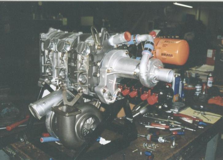
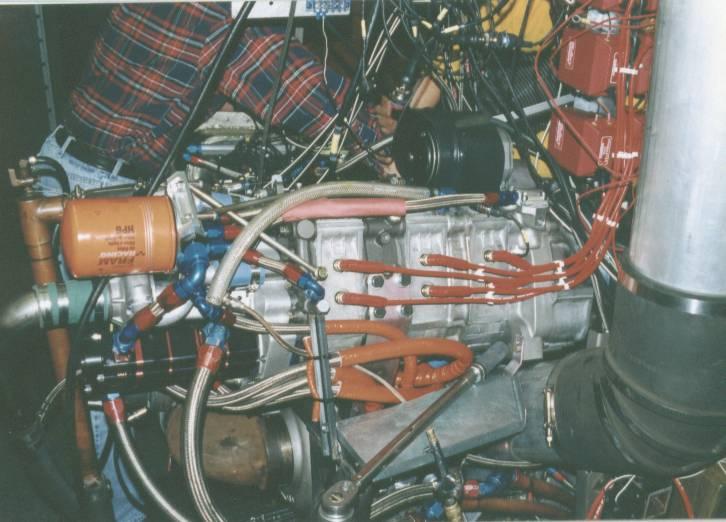
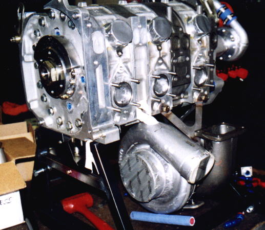
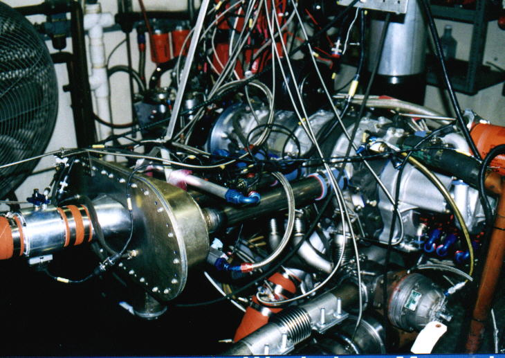
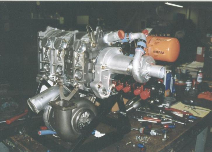
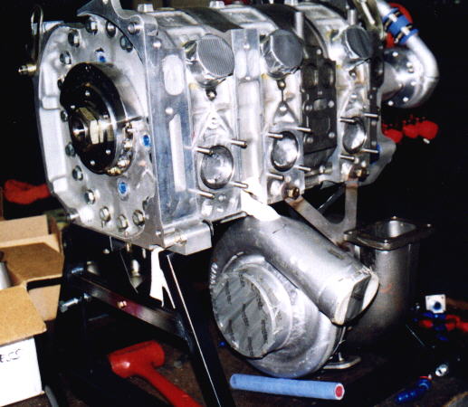
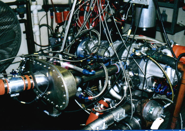
You are forgetting one thing. Rotaries have been boosted to extraordinary
manifold pressures. Take a gander at the size of the turbo charger on this 1200
HP 3 rotor engine. I am willing to bet the turbine in this turbo charger is
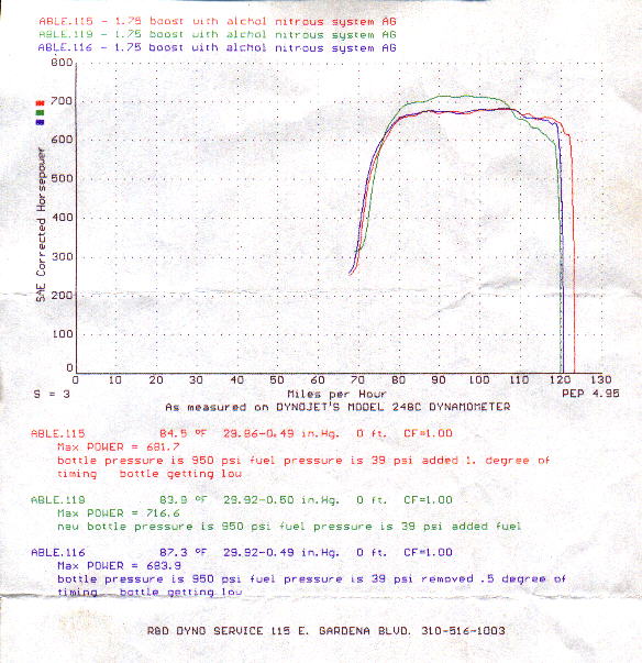
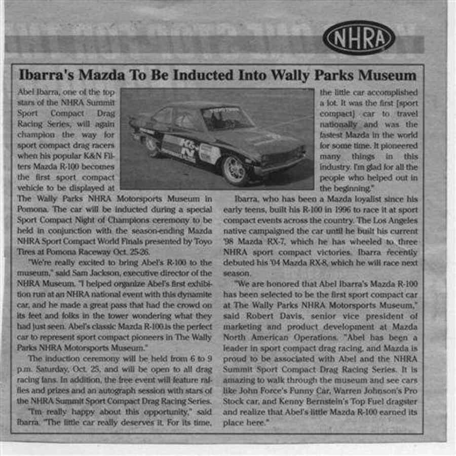
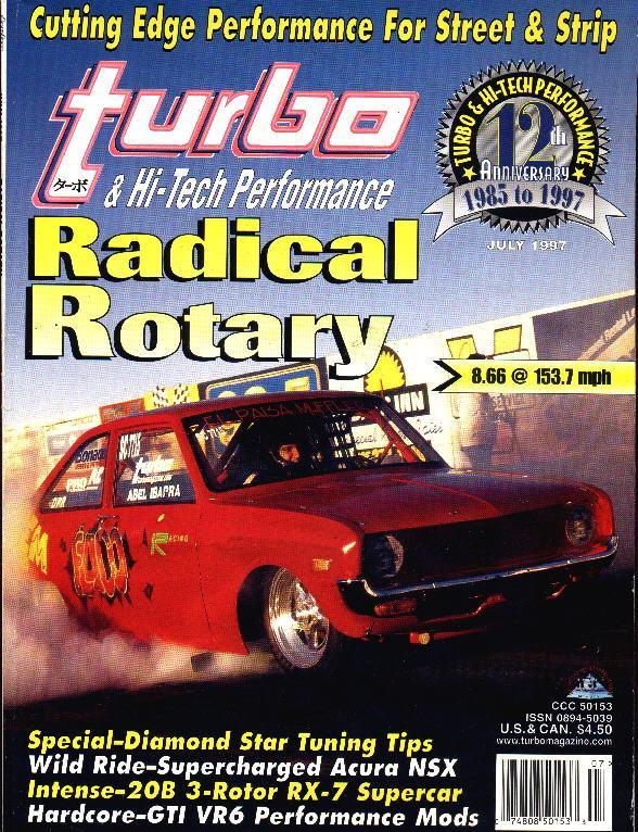
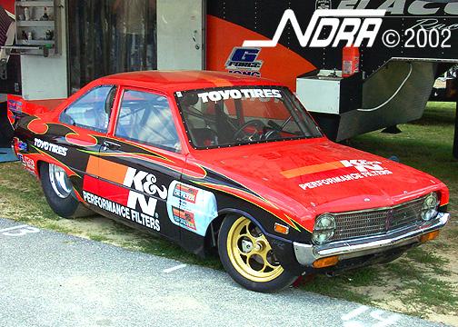
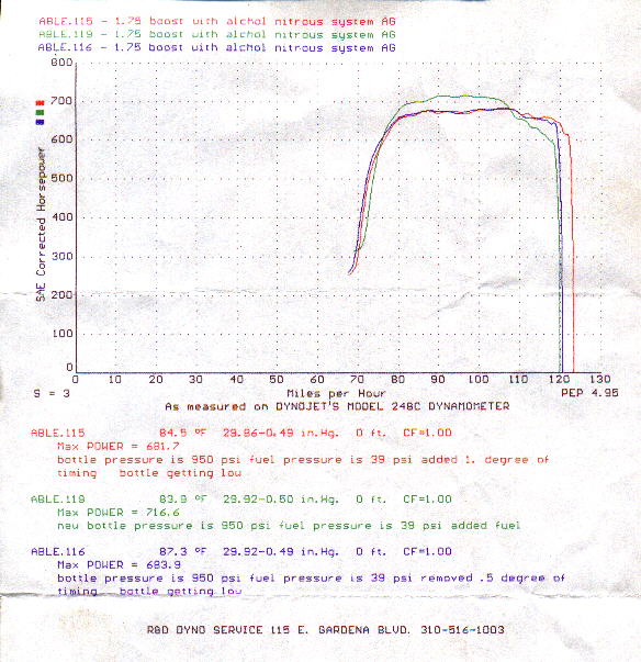
generating as much as 300 HP. Here too is a HP curve of a 1996 700 HP 2 rotor
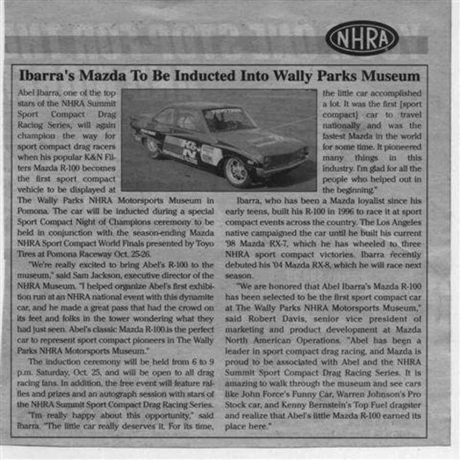
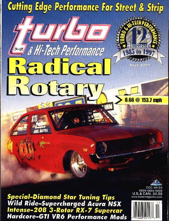
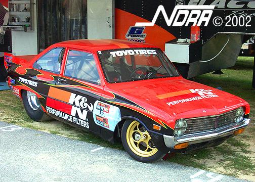
side port engine. The dyno sheet was given to me by Abel Ibarra hisself :)
Yes the engine was using alcohol and NOX but it still takes a lot of air to make
this kind of HP.
Paul Lamar
--
The Rotary Engine NewsLetter. Powered by Linux.
ACRE NL web site.
http://www.rotaryeng.net
Youtube key word UTUBPLEASE
Copyright 1998-2009 All world wide rights reserved.