Paul,
Thanks for the cooling book which gives so many practical ways
to
cure my problem. The wedge, does it taper to be flush with the rear of
the Rad,
or should it be up say a half inch? I assume that the inlet is to be the
magical 1/3 of the area of the Rad ? I expect that my actual inlet will
only be
about a foot before the rad, so is it better to go wider with the inlet
rather
than higher?
THe curve before the outlet on the firewall, I have heard of this
many
times, but have never been able to get a drawing. Have you dimentions
etc
available ??
Thanks for a great book. Met Fred Moreno at an Saaa meeting only a
month
or two ago. His Lancair is flying at last but with a Lyc!!. What
happened? He
now lives south of Perth which you probably know.
Neil.
----------------------------------------------------------
I think that may be a different Fred Moreno. Did he say he was on our
news
letter? If I had known he was there I would have tried looking him up
when
I was
in Perth early this year.
The end of the wedge must be right down on the core. In fact Ian out in
Perth
claims it is well worth doing the S curve trick. Second attachment Fig 4.
He has
reduced the size of his scoop drastically on his second RV6 and it is not
cool
in Perth during the summer time :)
http://www.youtube.com/watch?v=uZ4NqGv6SwQ
To answer the question on the size and shape of the scoop I need to know
how
fast your airplane flies. Slower airplanes can use larger openings to
cool
at
lower climb out speeds. Also the use of a cowl flap is a factor. A nice
cowl
flap will allow a smaller scoop. I assume you have an RVx something or
other.
BTW folks don't be taken in by the supposed need for a smaller pulley on
the
e-shaft to cut down the water pump speed. That may be true on a racing
engine
that is going 11,000 RPM but we never see more than 7500 with a 2.85:1
gear box
and 6500 with a 2.17:1 gear box.
Also there is a remote possibility that taxi cooling can be helped by
more
water
flow. Some body needs to do a little data taking on that subject one way
or the
other.
Paul Lamar
paul,
First I fly a sportsman with a climb speed of 90 kts and a cruise
speed of 135 kts.
Yes I have a cowl flap but advice on clearances front and back closed and
open will help. I have a 4inch stroke on the actuator at the back of my
cowl
flap.
page 50 just above Cowl flaps, "A large radius must be used on the
firewall"--- Have you any drawings or specs please.
The "S curve trick ?? Cannot find the attcahment. Page?? or
descritpion please
Neil
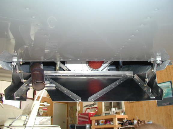
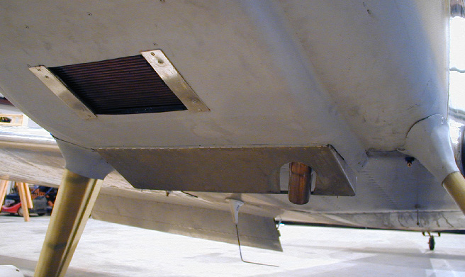
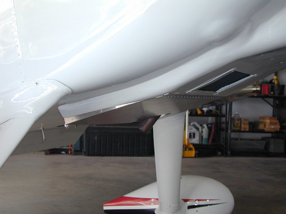
Make the radius as large as you can comfortable fit on there. Something
like 5
inches would be pretty good. Increase the cowl flap angle to 45 degrees
wide
open. It will not affect the climb rate. Here are a few pictures.
In the book the S curve is on page 36 Fig.4. No coordinates yet so you
have to
eyeball it. Also there is a furnace blower test duct S curve picture on
page 89
next to Mikey. Not a real good picture but you will get the idea. You can
use an
array of pitot tubes to survey the velocity distribution of the air flow
coming
out if your inclined. We always appreciate new data.
Paul Lamar
Paul,
so far so good, can you give me an idea as to the size opening of
the duct to the rad allowing that the rad is between 2 and 2.5 sq feet ??
Neil;
I would go for 30%. If it cools OK that you can try reducing it.
Here are some more pictures of cowl flaps.
Paul Lamar
--
The Rotary Engine NewsLetter. Powered by Linux.
ACRE NL web site.
http://www.rotaryeng.net
Youtube key word UTUBPLEASE
Copyright 1998-2009 All world wide rights reserved.