One of the vexing problems we have had for years was the difficulty of installing off
the shelf capacitor discharge ignition systems on the rotary. The very common 2nd gen
crank angle sensor put out only one pulse per engine rev while two were required. One
180 degrees out of phase with the other. One pulse for each rotor.
A four cylinder piston engine puts out four pulses per rev of the 1/2 speed cam shaft
and the distributor sends the spark to the right cylinder as needed and one CD system is
used. If we could somehow get two pulses 180 degrees out of phase we could use two CD
systems with the benefit of multiple sparks at a
much higher RPM than would be possible with a 4 cylinder engine and a single CD system.
Yes we could use two trigger wheels on the e-shaft and two sensors mounted 180 degrees
out. The spark wheels would have to be slotted so the spark timing could be adjusted.
The 2nd gen CAS has two sensors and it is already slotted for timing adjustments. They
are a dime a dozen on e-bay and are the most common way of triggering rotary engines.
The top sensor puts out one spark per E-shaft rev and the lower sensor puts out 12
sparks per E-shaft rev. The lower sensor is used to send RPM data to the computer. Why
does the top sensor have two tits on the trigger wheel? Simple! The CAS runs at half
E-shaft speed left over from the days when the rotary had a distributor.
What I have come up with is a simple and cheap two chip counter circuit that counts six
pulses on the lower sensor and puts out one pulse for the second rotor. Ideally I'll
sell an assembled PC board unless someone else wants to do it. We don't need variable
advance as the engine runs in a narrow RPM range of 5000 to 7500 RPM and real aircraft
engines don't have variable advance. If you want variable advance get a computer and
program it yourself :)
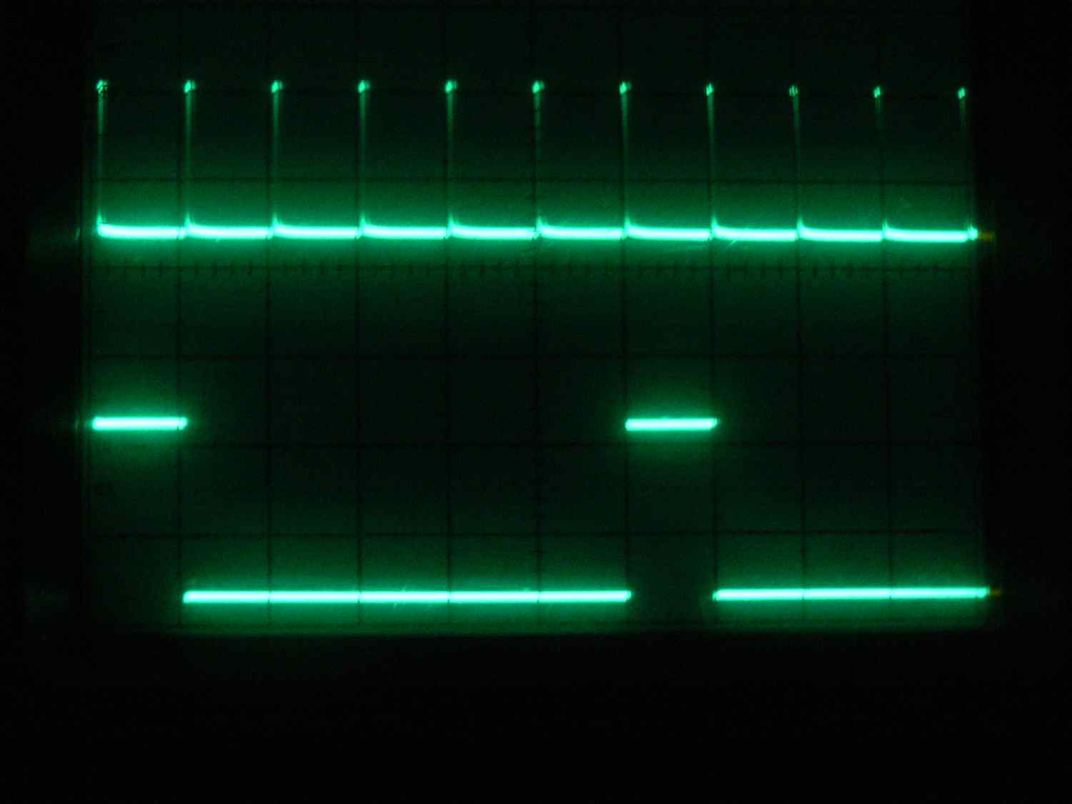
Here is the timing diagram. The counter chip I will try to use is a CMOS 4017 decade
counter. A hex inverter chip will provide both positive and negative going triggers for
different CD systems depending on their needs.
http://www.kpsec.freeuk.com/components/cmos.htm#4002 The count advances as the clock
input becomes high (on the rising-edge). Each output Q0-Q9 goes high in turn as counting
advances. For some functions (such as flash sequences) outputs may be combined using
diodes.
The reset input should be low (0V) for normal operation (counting 0-9). When high it
resets the count to zero (Q0 high). This can be done by the top trigger pulse.
The disable input should be low (0V) for normal operation. When high it disables
counting so that clock pulses are ignored and the count is kept constant.
-------------------------------------------------------------
With the right drill motor you can pull the roll pin and gear and chuck the CAS for
testing the circuit. The shaft diameter is just under 1/2 inch.
BTW you can use two CD systems on the leading plugs and two Corvette style LS1 coil on
plug systems for the trailing plugs I think. I'll have to test that as I think the coil
on plug systems require a certain limited dwell time. I suspect if the dwell time is too
long the GM coil on plug systems over heat. In that case perhaps a couple of 555s will
put out a fixed pulse width to the coil-on-plug systems. One can always use 4 CD
systems. Racing Beat uses 4 CD systems on their racing engines. Six on a 3 rotor.
Also BTW I have a report on the GM LS1 coil on plug systems: "Turns out that LS1
igniters always draw power whenever available. Not much -- only about .02 amp each. But
that will (and did) drain the battery over time for sure. So I rewired to put a switch
inline to disable them the same way the injectors need a similar switch to not keep
sucking juice. Ammeter and voltage level testing now confirm batteries don't get run
down anymore."
Paul Lamar
----------------------------------------------------------------------
Or, grind off all but 2 of the 12 gear teeth for the bottom pickup coil.
Run the MSDs from each of the coils.
The top pick up for the front housing and the lower pick up for the rear
housing. Have the MSD drive a double ended MSD (or other suitable) coil to
fire both plugs at once.
No advance curve is required. The engine will start and run fine with
anything from 20 to 27 degrees of advance. Mark out two sets of timing marks in
the spaces between the teeth on the flex plate. One set for the front
housing and one set for the rear housing. Use epoxy paint. Very easy to see.
Make a fixed pointer on the PSRU mounting plate.
Keep the plug wires short and use spiral core wire.
Lynn E. Hanover
That will work no doubt but it makes a mess if you do it while the wheels are still in
there. Easy to have the die grinder slip. If you take the shaft out it is a fair amount of
work to take it out and put it back in.
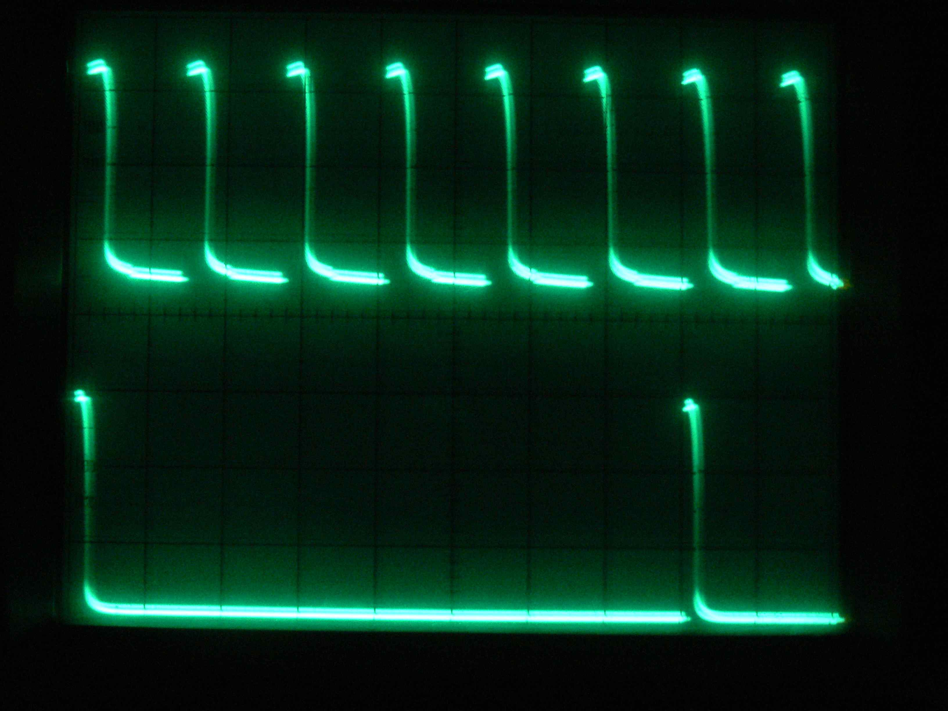
I like my electronic way as it gives more flexibility on the type of output trigger. Up or
down and width. Here is the counter out put and the final output trigger for the lower
pickup or rotor 2.
Take your pick. Both ways will work.
Paul Lamar
--
The Rotary Engine NewsLetter. Powered by Linux.
ACRE NL web site.
http://www.rotaryeng.net
Youtube key word UTUBPLEASE
Copyright 1998-2009 All world wide rights reserved.