This is an array of standard .2 inch diameter infrared
photo transistors and LEDs. There is a slot in the slide
that allows the light to travel from one LED to its corresponding
photo transistor. Very simple and straight forward. These parts
are about 80 cents each. This gives slide throttle position
to one part in 16 or 1/8th of an inch. Two $2 chips called a
8 bit priority encoders are used to out put a 4 bit
(1 part in 16) binary number to a parallel input port.
The advantage of this approach is you know
where the throttle is and you know if it has moved quickly
so an enrichment pulse can be sent to the injectors to
prevent stumble. It is possible one could do away with
the manifold pressure sensor and just use this information
along with RPM to adjust the mixture.
This is a piece of cake for a DOS-QB EFI system.
The parallel port is read by one statement called
a PEEK in QB. QB can tell how fast the throttle
is moving by recording the last time it was moved
and subtracting that time from the next time it moves.
If it is less than a .1 second than somebody jammed
the throttle open :)
Paul Lamar
Paul.
O.2 inch is about 5mm. I have seen 3mm ones and their might be smaller
ones available. You could also accomplish the same thing with one
optical reader like my torque sensor idea. Have it read dots, or
patterns that correspond to binary numbers.
Doug in Japan
I was just going on what DigiKey was offering. It would be nice if they
were smaller. I could not find any. Got any data on your optical reader?
I have had problems with optical readers in the past and I have
found the interrupter design to be more reliable. The one side optical
readers is sensitive to ambient light level. The other advantage to this
approach is the current slide throttle covers provide the package and
holders for LEDs, photo transistors and the PC boards. No device needs
to be mounted or attached to the throttle cable. I might offer a kit
way down the road if enough people are interested in the PC DOS-QB EFI.
It can be retrofitted to current slide throttles that are out there.
Paul Lamar
How about this:
4 photo diodes, 4 LED's. Mount them in a single line perpendicular to
the axis of the slide. Binary encode the position by drilling lines
of grey code holes across the array. Grey code so that transitioning
from one position to the next only changes one bit of the code -
eliminating spurious glitching. As the slide moves, a different count
is made present across the photo diodes - no other encoding required.
At one end of the slide, only one hole, at the other end of the slide,
4 holes (16 counts).
To deal with radiation contamination (that's DC offset/drift), the
emitters (LED's) should be modulated at something like 20kHtz, and the
photo diodes should have a simple high pass filter driving a follower
(buffer) driving a rectifier and low pass filter, driving a
comparator. Have to look at the datasheets to see the response curves
to pick a good frequency. It might be helpful to turn on only one
emitter at a time and read only that emitter's photo diode at that
time - to reduce the chance of contamination from one to the next.
The computer can easily switch between them fast enough to not miss
any movement.
Matt-
Draw it up Matt. I would like to look at it.
If there is any width to the place where the holes go that could
interfere with blocking the intake ports. I explored that and gave up
on it for that reason. I drew it out to scale. The current scheme
needs only one narrow slot in the slide.
Paul Lamar
Why not just build it up as a unit separate from the slide throttle and
place it in the cockpit and mechanically connect it to the throttle cable?
Joe Berki
More work. More time.
--------------------------------------------------------
OK I found some smaller transistors. This reduced the
area needed on the slide throttle.
Here is a pdf on the transistors and a few 3Ds of the
slide throttle position sensor.
I can use the MTIME function in PB to tell when somebody has slammed
the throttle open.
Paul Lamar
Hi Paul;
This is email recycle day.
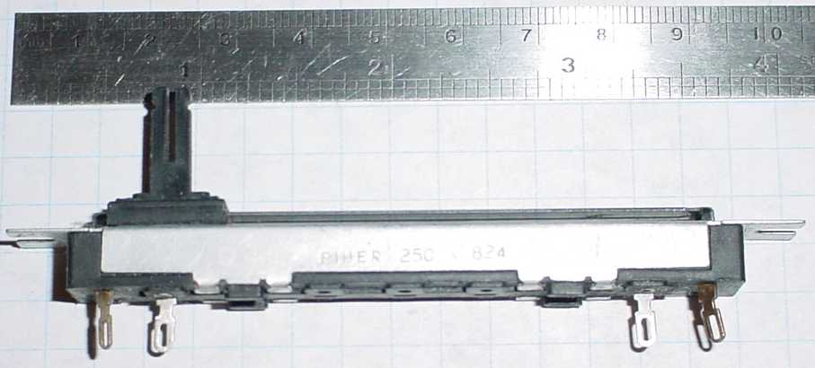
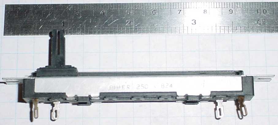
Here's an off the shelf Piher linear slide POT as used in old sliding AM/FM radios.
Useable travel is 2-3/8" with this one. Got a few for a buck or two.
With a large PPort, the MAP signal may be weak/poor at low rpm.
(who made their PPort too big ;) A throttle position sensor (TPS) would be useful for an
Alpha-N tuning setup
(throttle position versus rpm).
It also provides another primary/backup sensor for a possible limp home mode.
There are more rugged industrial and milspec versions. Here are a few
from a 30s google:
http://www.maureyinstrument.com/linear-prods.asp
http://www.specsensors.com/linear.asp
http://www.celesco.com/linearpot/index.htm
Cheers
Cary
Well it requires an A to D. I am down to just a printer port for
hard ware. No A to D. So I need digital position data for the
slide throttle.
BTW I got the par. port working in PB but apparently both busy and out
of paper input pins need to be tied low. With no printer hooked up they
are high or five volts. I think that is done in the printer
port hardware so I think I may have just lost the use of 2 input
pins. In any event I can now send data out of the par. port in about
one micro second. This short program outputs a square wave once :)
I am not sure the def seg is needed yet.
'busy and out of paper need to be low
CLS
MTIMER
for y = 1 to 10
def seg = 0 'stupid Intel seqment architecture
out 888, 0
def seg
next y
for y = 1 to 10
def seg = 0
out 888, 255
def seg
NEXT Y
ElapsedTime!=MTIMER
PRINT USING "iT TOOK ##### MICROSSECONDS";ElapsedTime!
Paul Lamar
--
The Rotary Engine NewsLetter. Powered by Linux.
ACRE NL web site.
http://www.rotaryeng.net
Youtube key word UTUBPLEASE
Copyright 1998-2009 All world wide rights reserved.