Hi all
I worked from 1968 to 1993 on Rotary Engine
One item always eluded me and that was working out the CR and for purely
academic reason I would like to complete this program, I would be
grateful
if you could give me some worked examples data.
R'=R+a : e : B : Radial flank clearance : Width clearance & finally rotor
pocket volume.
In my worked example based on the Norton Rotary
R'= 71.5 mm e= 11.6 mm : B=68.2 mm : Flank Clearance = 0.5 mm : side
clearance = 0.15 mm , the compression ratio's ranged from 7.5 to 1 &
9.2 to
1 do you have any examples that also include combustion pocket size, or
could you please measure the rotor pocket volume, and tell me the alleged
CR.
We used to measure this for D.Garside and I would give him the volume
of a
Plasticine by filling pocket, scrape around the flank with a steel
rule, and
then measuring the fluid displacement,
It is possible that no two formulae give the same results.
I have worked out the flank clearance Volume, but just need some actual
rotor pocket volume, and the R'=R+a : e : B= width and the : posted CR
Example R'= 10.5 cm : e=1.5 cm : B or width 7 cm
Raw CR = Best possible ie, no combustion pocket or flank clearance = CR
18.29 to 1
Flank Clearance = 0.050 cm = CR = 15.41 to 1
As above but with volume in rotor pocket = 35 cm = CR = 8.66 to 1
If flank clearance set to zero and pocket volume = 35 cm = CR = 9.41 to 1
But you should include for the pocket volume and the spark plug/s
recess and
also the Land clearance, sometimes called top land clearance in piston
engines.
And the only way to test the program is by having as many types of engine
data and Chamber Volume and CR
Bob Rowley
Tamworth
UK
The volume varies with the year. A rotor I have
here in my office is 10 mm deep. Mean width is 48
mm and it is about 77 mm long. CR is roughly 9.6.
Housing width is 80 mm.
You can download Kenichi Yamamoto's book "Rotary Engine" from this
web site. It contains most of the dimensions on the Mazda rotary.
http://foxed.ca/foxed/index.php?page=rx7manual
Here are a couple of excerpts.
Other info is scattered throughout the tech papers on our site.
Paul Lamar
Hi Bob;
Be wary of formulas errors in both the '71 and '81 editions of KY's
Rotary Engine books.
Here is an old email on the error in the volume formula.
'81 Edition, page 14, Section 2.4.2, bottom right - formula 2.24
V=volume
e=eccentricity=15mm
R=Generating circle radius= 105mm
b=width of rotor housing= 80mm
alpha= degrees eshaft rotation
Vmin=minimum volume at TDC (long formula 2.25) =~ 56.5cc or
in the case of a 9.4CR rotor 654/(9.4-1)= 77.9cc
V = Vmin + ( 3 * root(3) / 3) * e * R * b ) * (1 - sin(2/3 * alpha +
pi/6) )
Formula makes more sense if you look at Figure 2.9 on page 15. Shows
the chamber volume
changes as a sine wave based on eshaft rotation compared to a piston
engine.
I just noticed the formula is different in the '71 edition.
3 * root(3) * e * R * b =~ 654cc (swept volume) - the "/ 3" term
appears to be incorrect.
The "/ 2" in the '71 edition appears to be correct.
Still need to work out the intake close timing angle. Not sure if the
alpha value can be replaced with the
degrees of eshaft rotation?
Thanks
Cary
There are errors every once in awhile in the book.
I am not sure I understand the goal here.
I have a lot of intake timing diagrams for both the side
ports and the P-ports verses VE.
Perhaps the angles are expressed in radians and not degrees.
Hi Paul;
When I originally did port timing for the Pport I had to estimate.
Stock port timing are available at:
http://www.yawpower.com/dectech.html
I have seen some of the Pport intake timing diagrams vs VE from some
of the old Mazda tech papers
posted here occasionally - don't recall seeing the diagrams for the
side ports.
I wanted to confirm what the upper limit was for intake port close
angle that intake inertia has to overcome
before compression in the chamber starts pushing it back out when the
intake port is still open.
Had to work backwards to get the degrees of eshaft rotation. Values
look reasonable, I think?
Intake BDC Vmax = 77.9cc + 654.7cc = 732.6cc
30 ABDC - V = 711.8, Vmax/V = 1.029 (6 port 2ndary IC)
45 ABDC - V = 687.2, Vmax/V = 1.066 (40,50 approx side port IC)
60 ABDC - V = 654.1, Vmax/V = 1.120 (RB street port IC)
70 ABDC - V = 627.7, Vmax/V = 1.167 (6port Aux high speed side port,
RB JBridge)
75 ABDC - V = 613.4, Vmax/V = 1.194 (Mazda Factory PPort)
Does anyone happen to know the location of the 13b oil injection port
in degrees ABDC?
Might be useful as a manifold pressure gauge tap.
Cheers
Cary
We are already using it for the manifold pressure for Tracy's EFI system.
Works great. I have some nicely machined metric fittings for sale for that use.
I don't know what the timing is but it clears the welded p-port by
about 1/4 inch. Hint Le Mans timing.
Paul Lamar
Hi Paul;
These were quick email recycles from 06/07. The quotes got lost between
us and the internet.
Oil injection ports are something like 90deg ABDC, I would have to
measure housings again or dig through notes.
One of the problems with PPorts (and other engines) is the weak / poor /
erratic MAP signal, particularly at low rpm.
Hence Alpha-N tuning.
As folks are finding out, there are MAP sampling issues with the EC2 and
other systems, even with tubing or can style damping accumulators.
In some cases, you can be better off measuring ambient MAP for tuning
due to dynamic / transient effects.
The exact position of the oil injection port + MAP (max) can also be
useful as a (VE) Volumetric Efficiency measure based on the KY formulas
above.
Cheers
Cary
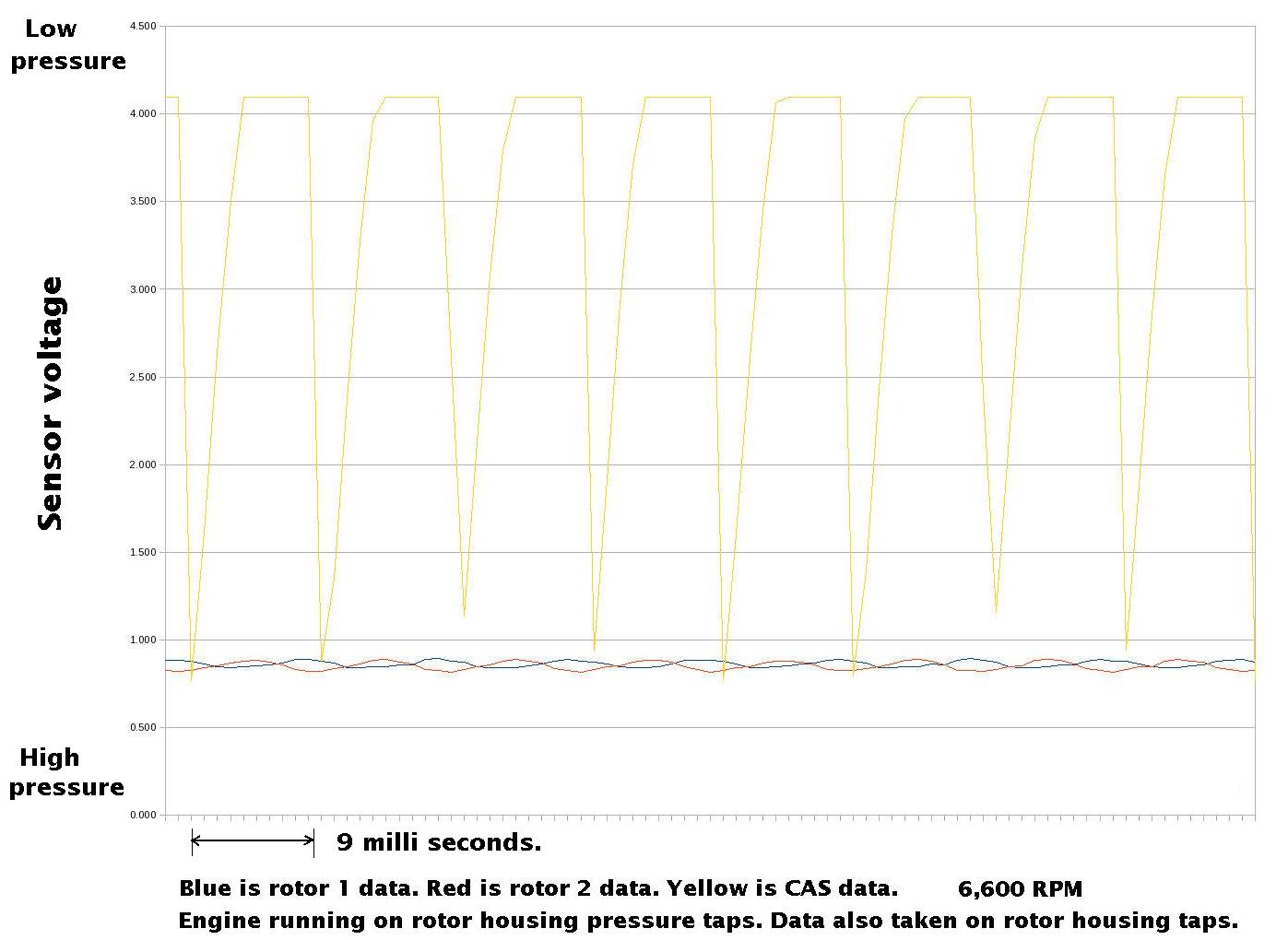
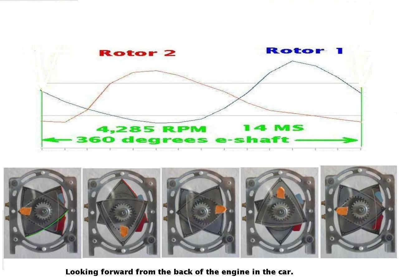
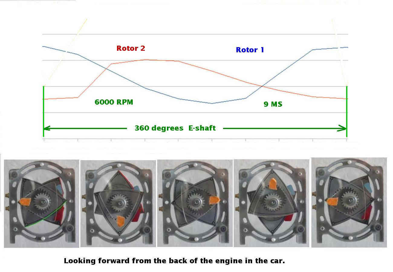
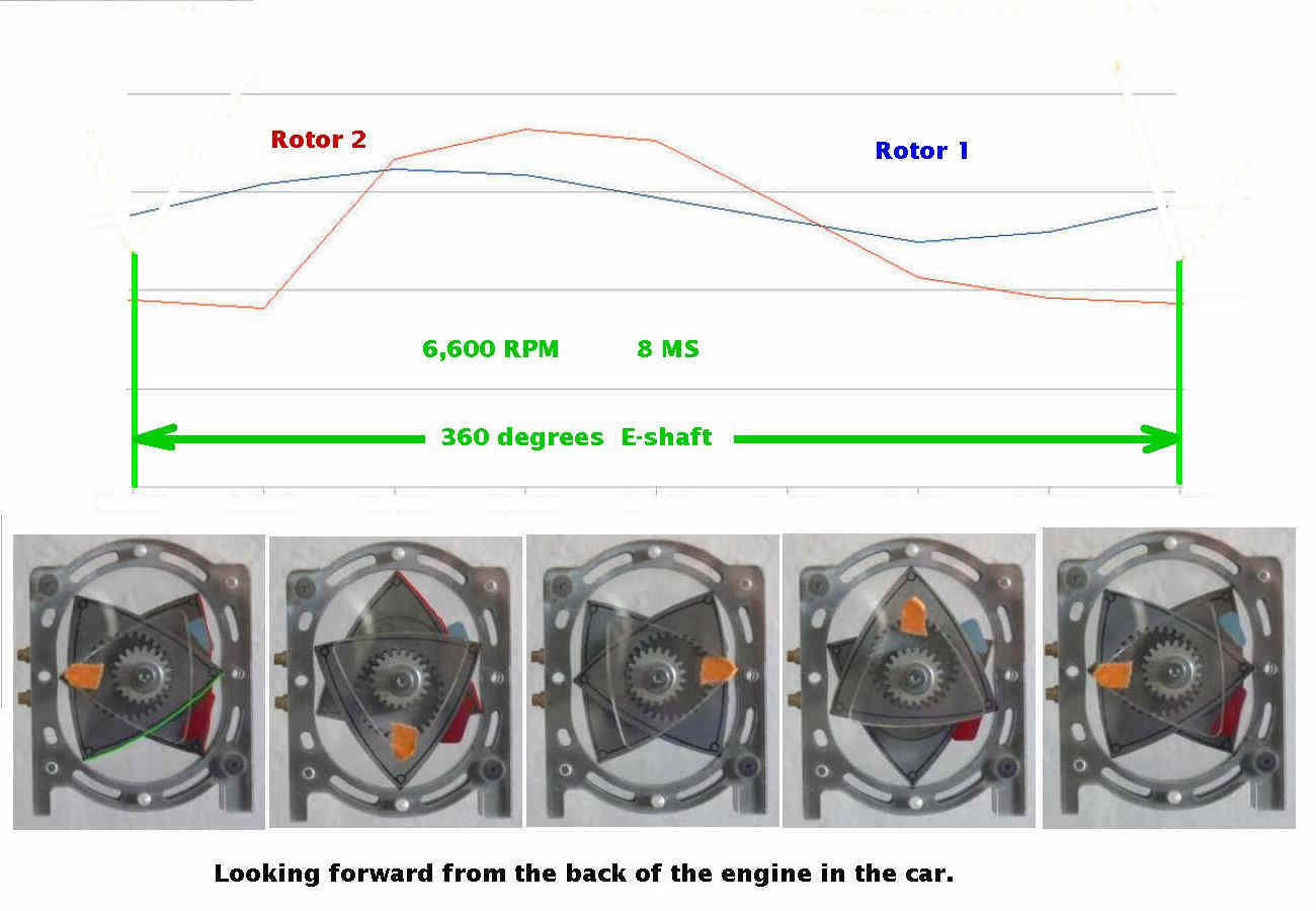
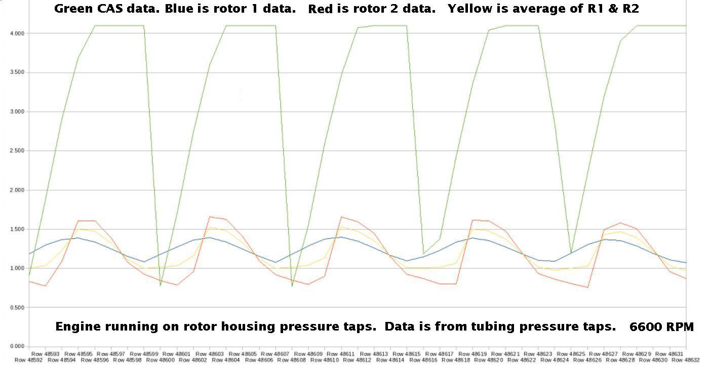
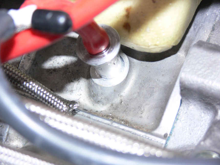
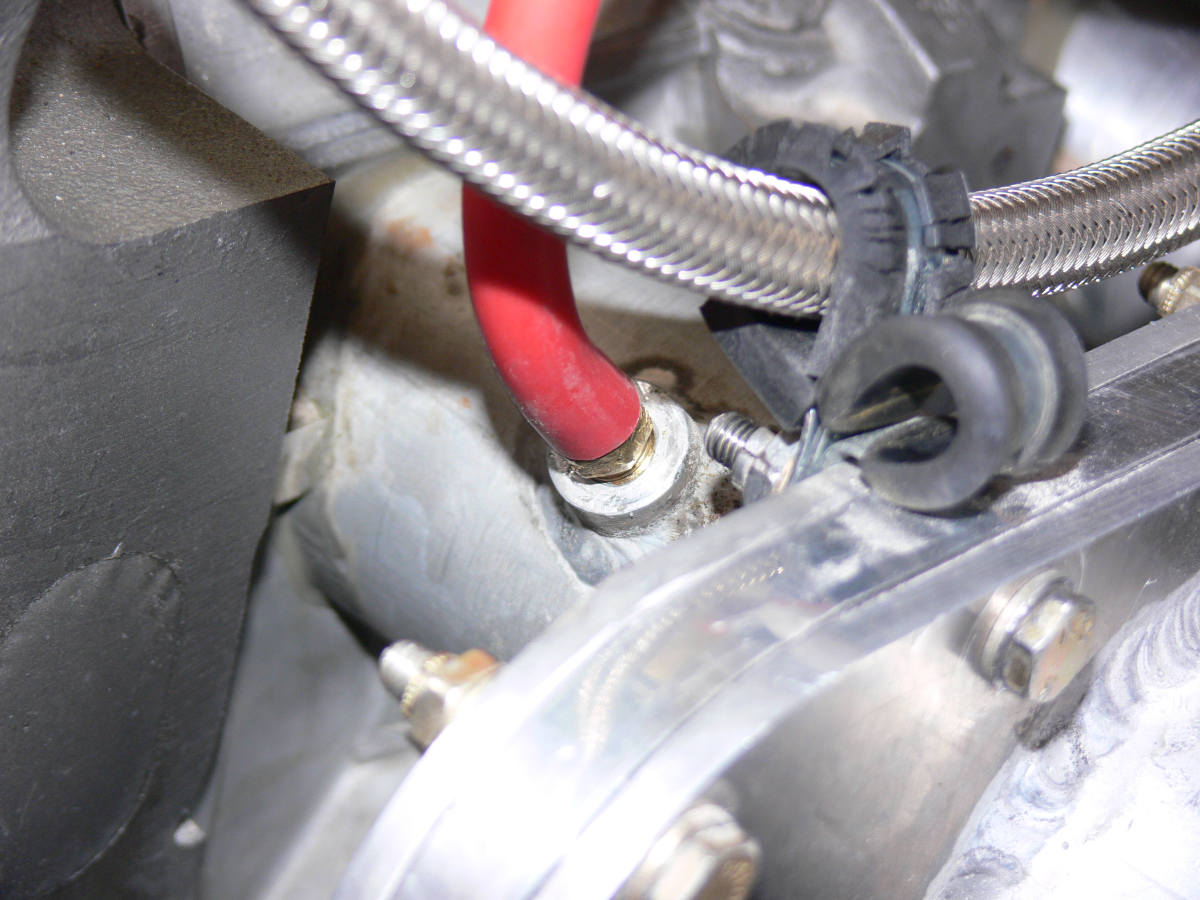
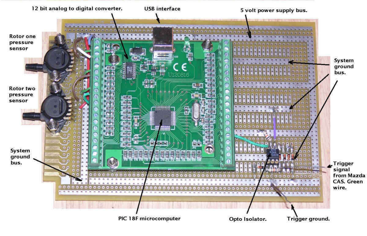
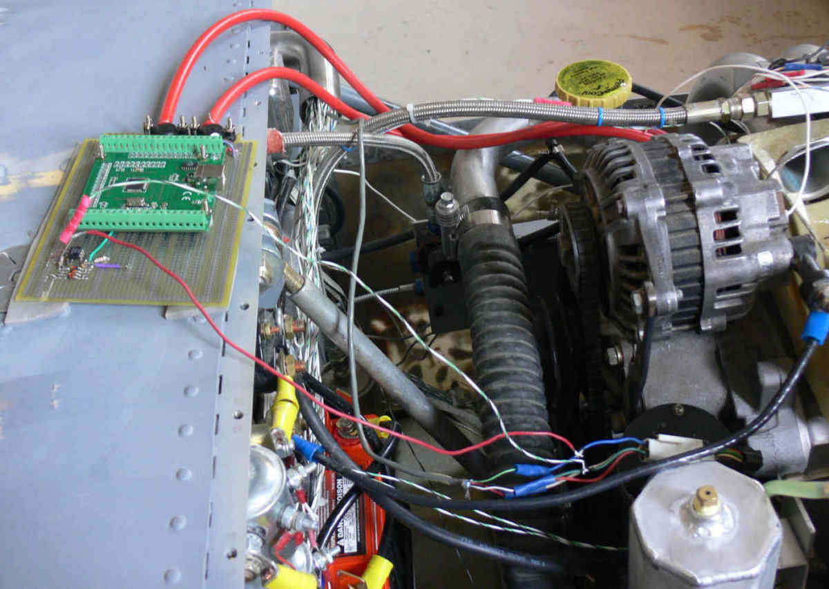
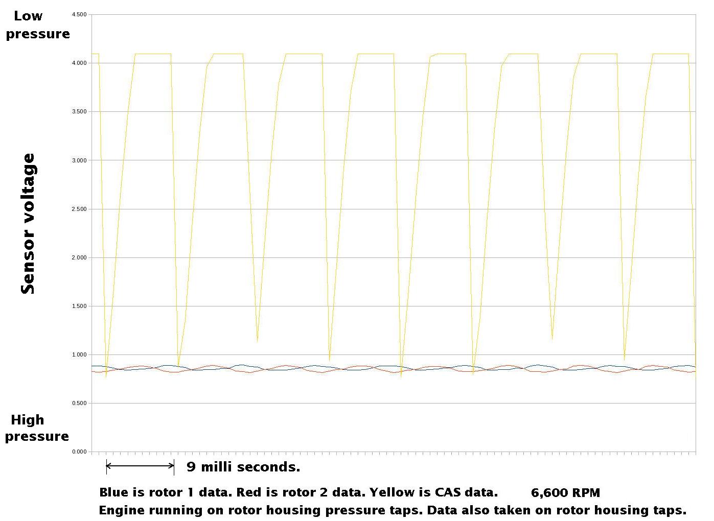
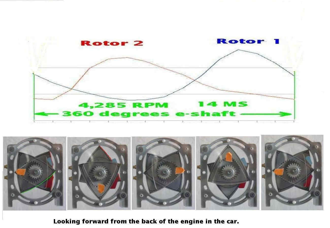
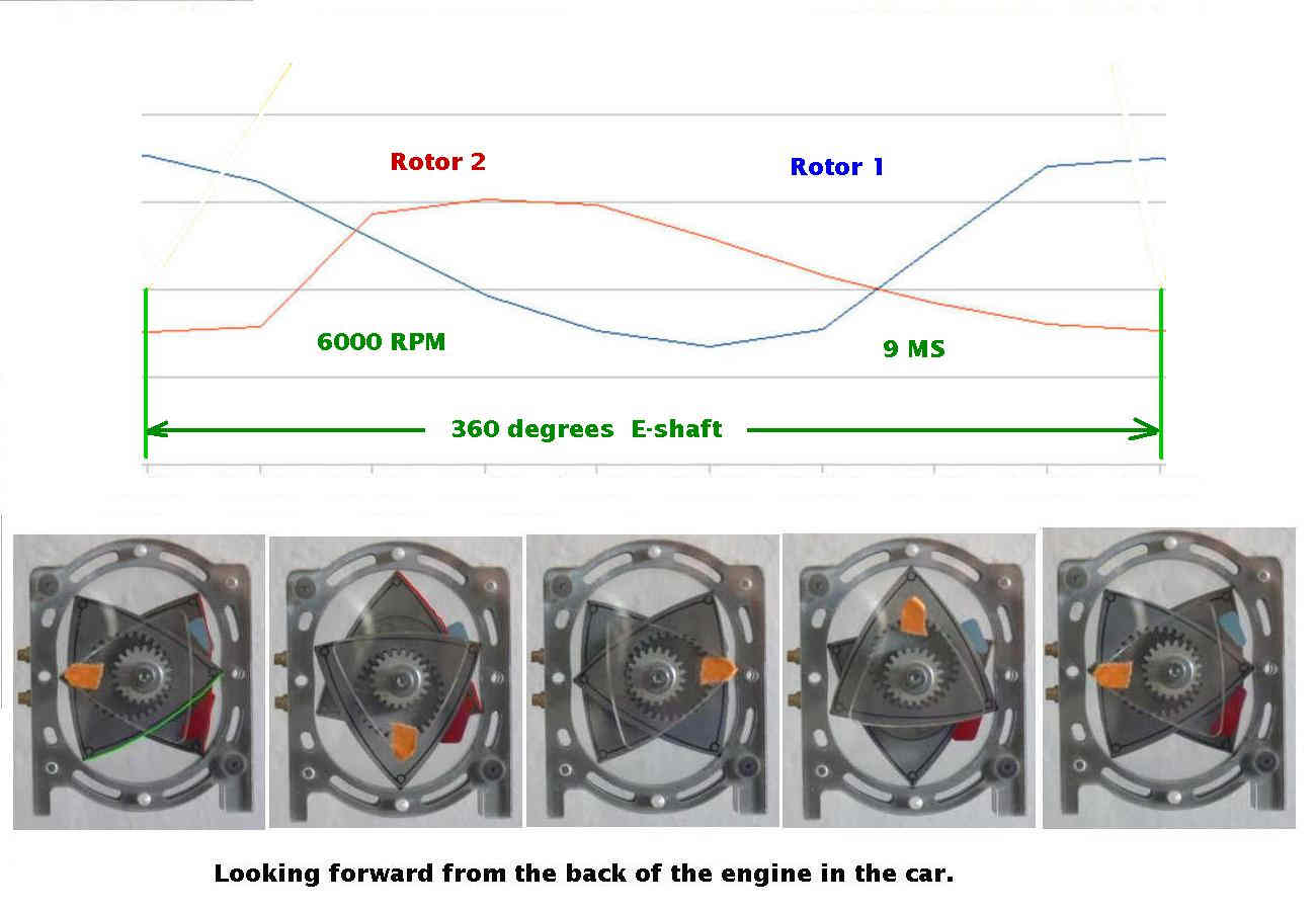
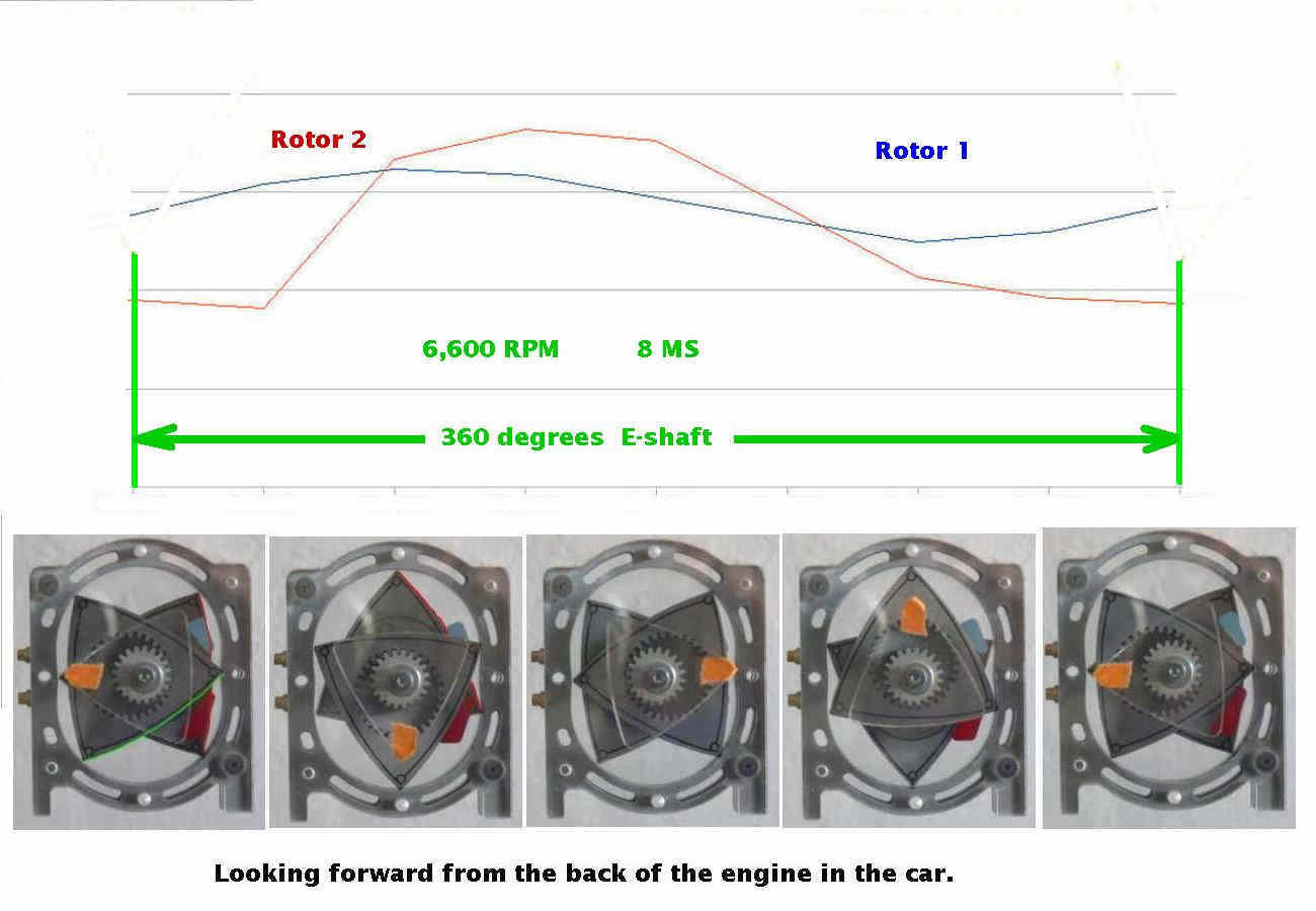
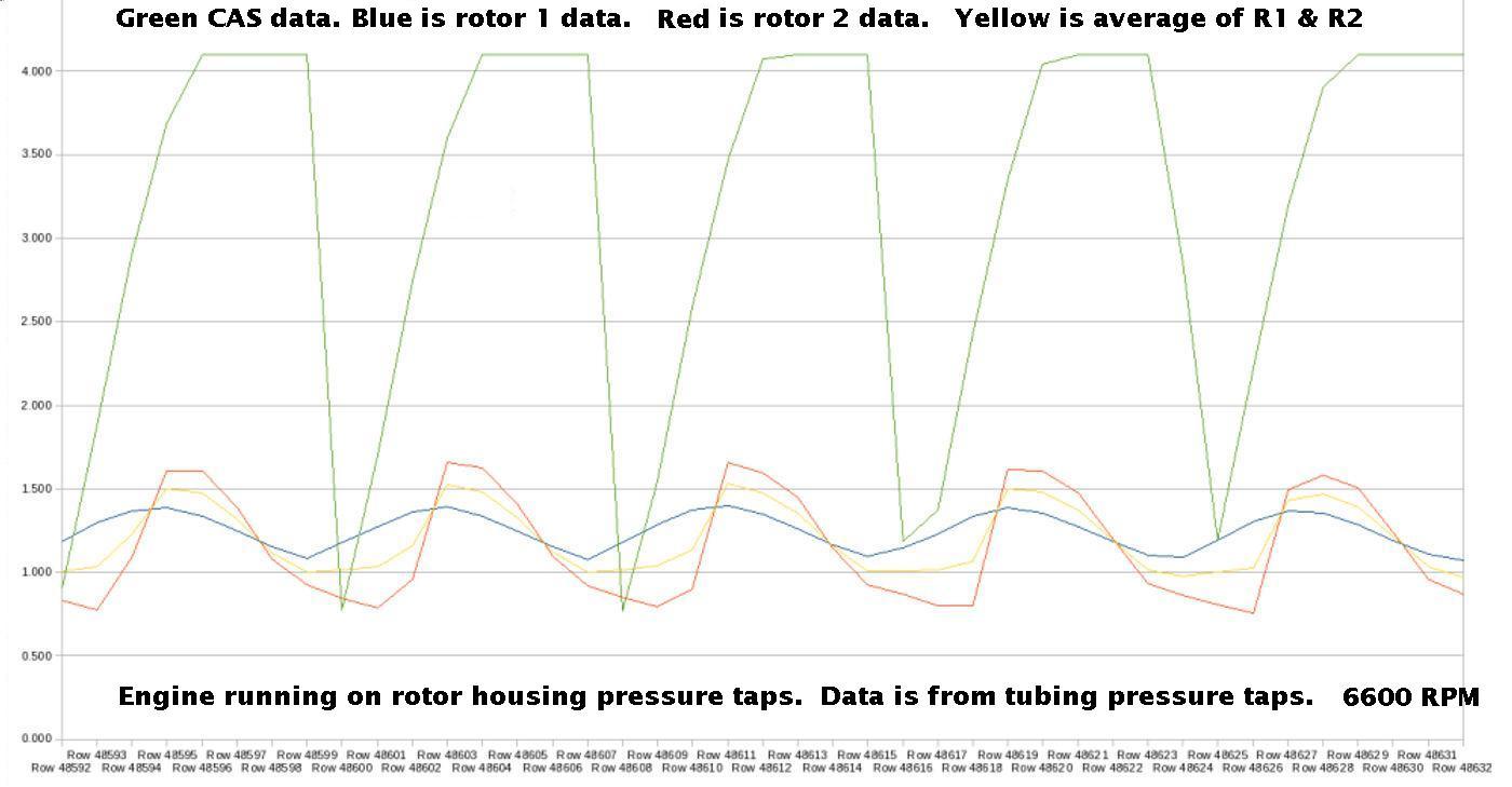
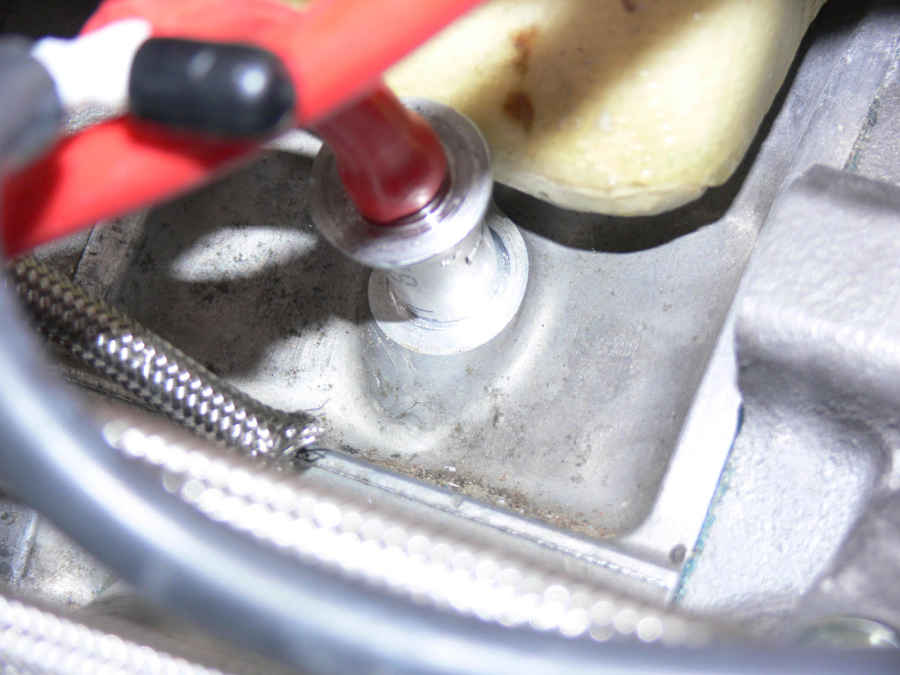
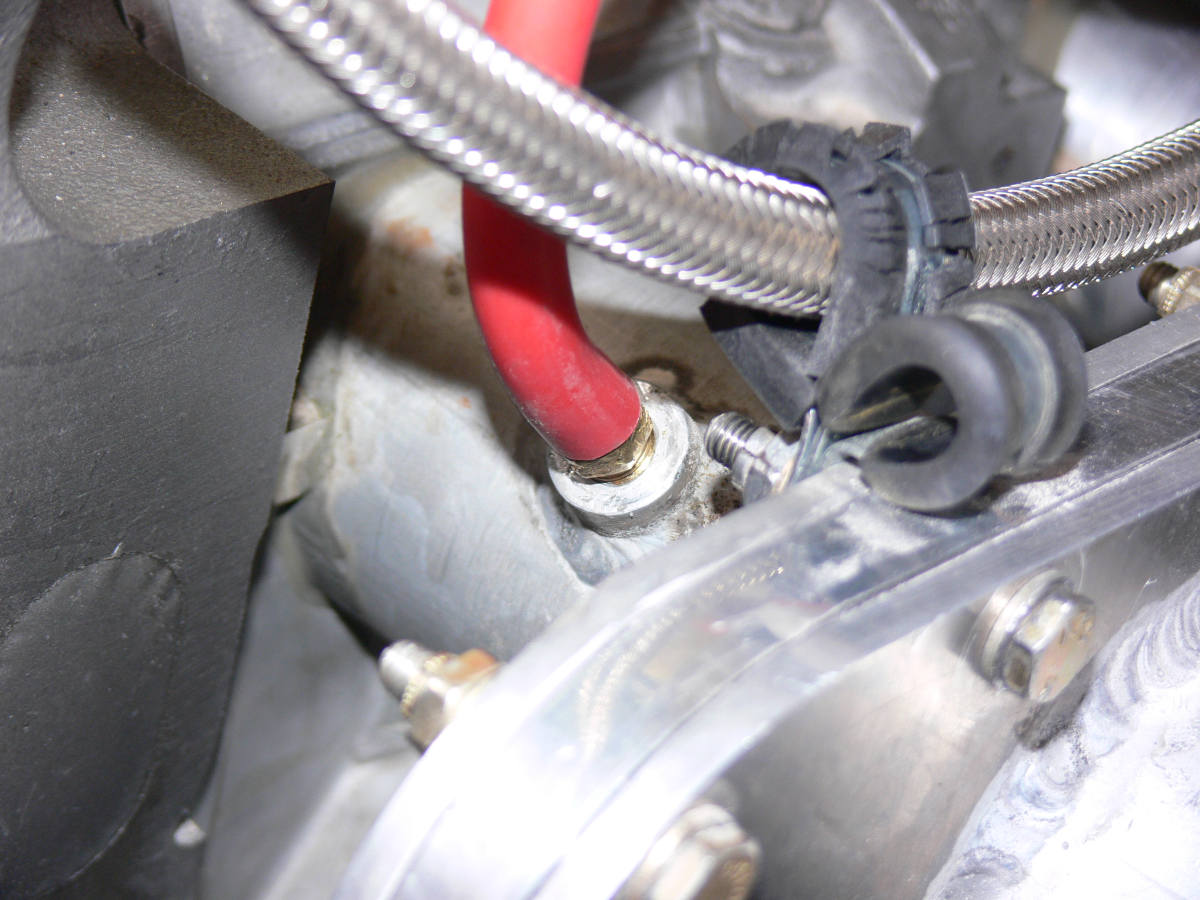
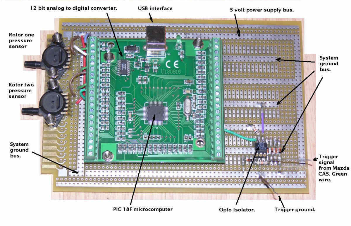
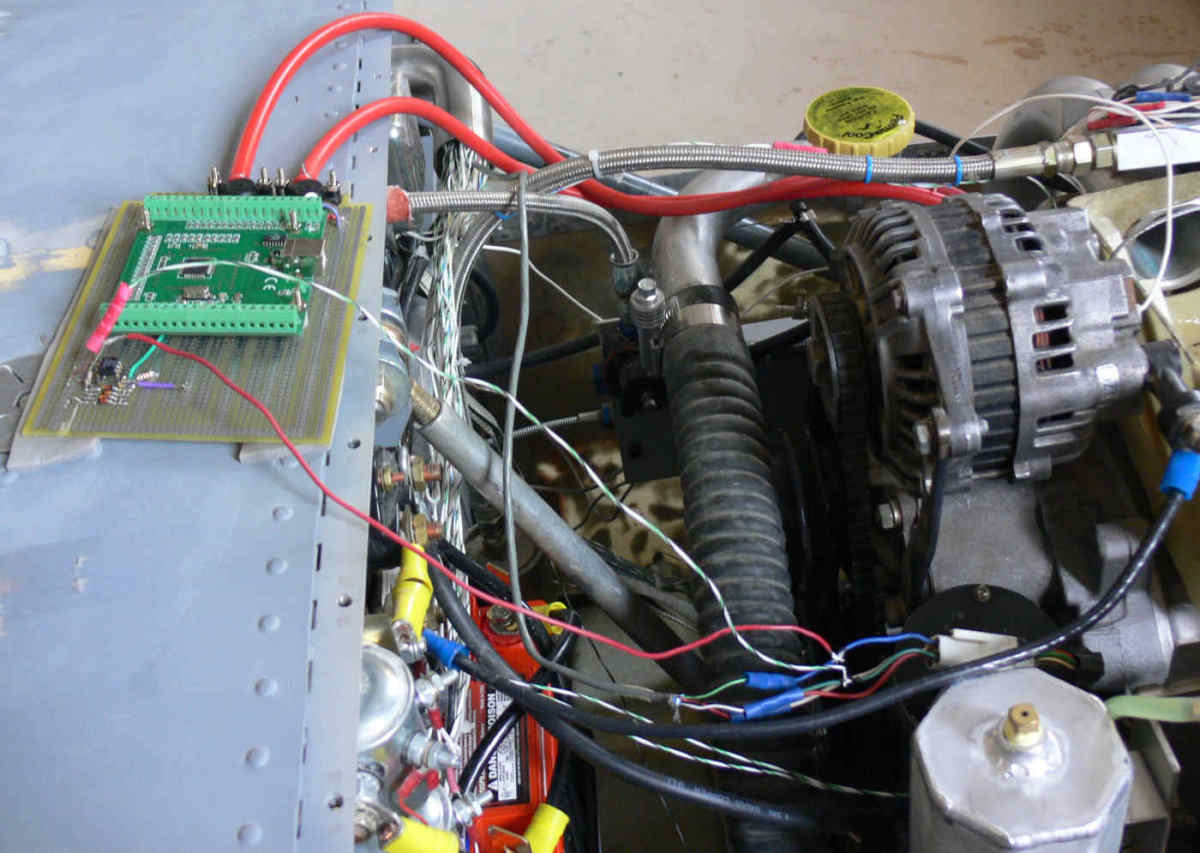
We took some high speed (1000 samples per second)
pressure data inside the intake tubes and through the oil injector
port. The oil injector port won hands down :) What really runs great is
an RX8 intake p-port engine with side exhaust. As good as any
13B.
The voltage numbers on the left sides of the charts are right
out of the pressure sensors. The same ones Tracy uses. A low voltage
number is high manifold pressure, high power and a high voltage number
is low manifold pressure, low power in absolute terms.
High voltage numbers would be high vacuum low power.
Paul Lamar
Paul Lamar
--
The Rotary Engine NewsLetter. Powered by Linux.
ACRE NL web site.
http://www.rotaryeng.net
Youtube key word UTUBPLEASE
Copyright 1998-2009 All world wide rights reserved.