Mark,
What Modine model number are you using for your 20B side port?
I have two long narrow oil coolers (2"Thick x 5"W x 20L cores) each of
which was normally found with a turbo charged 20B. I hear they are
getting rare. I would rather use one under the engine and duct straight
out the bottom.
Doug in Japan
----------------------------------------------------------
Doug,
Sorry, I don't know the model number of the Modine cooler. Core
dimensions
are roughly (from memory) 10" x 10" x 3".
Mark S.
------------------------------------------------------------------------------
Paul,
I am considering Setrab once I get a ball park idea. At this moment with
a good clean design I am shooting for over 400 cu. inches.
Cheers Doug
-----------------------------------------------------------------------------
The ES has a very generous size cowl so there is plenty of room behind it.
The worst thing about it is it looks at the red hot exhaust pipes.
Paul Lamar
--------------------------------------------------------------------
Paul,
Thanks.Mark has a
nice inlet but like Dave Leonard it exhausts to inside the cowl which
is rather restrictive on the back side. At 280 hp max that is also
the same approximate ratio as Dave at 1.07 cubic inches of cooling to
each hp. May not be enough on a hot day and long climb.
Cheers
Doug
-------------------------------------------------------------------------------
Hi Paul, Mark.
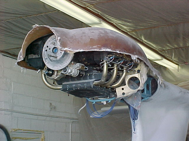
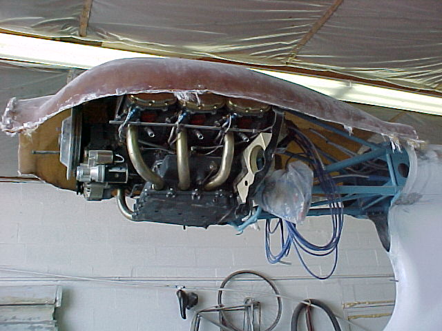
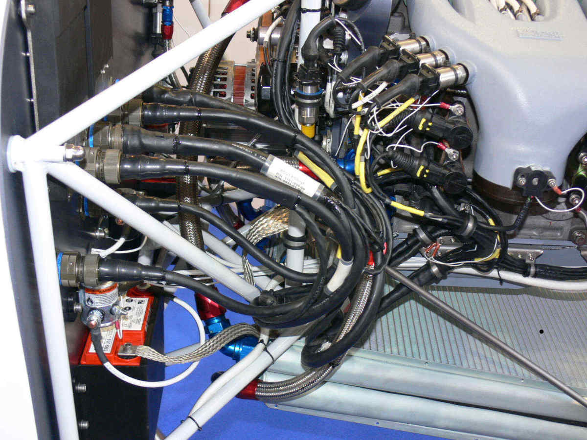
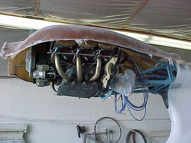
Based on Marks comments I believe the ten x ten inch by three inch unit
is the one mounted on the rear starboard side of his fire wall and its a
water and oil combination unit. It is shown in the picture I labeled
"Mark-ES-left side." There doesn't seem to be much of a gap behind
it.
The one on port side is bigger in cross surface area and is only for oil
I think. This was the one that wasn't functioning and the one I wanted
the dimensions on. Wetted area (minus the tanks) looks like about 11"
wide and 13" something high. Two inches thick is standard. Mark is
that about right?
Why all the fuss?
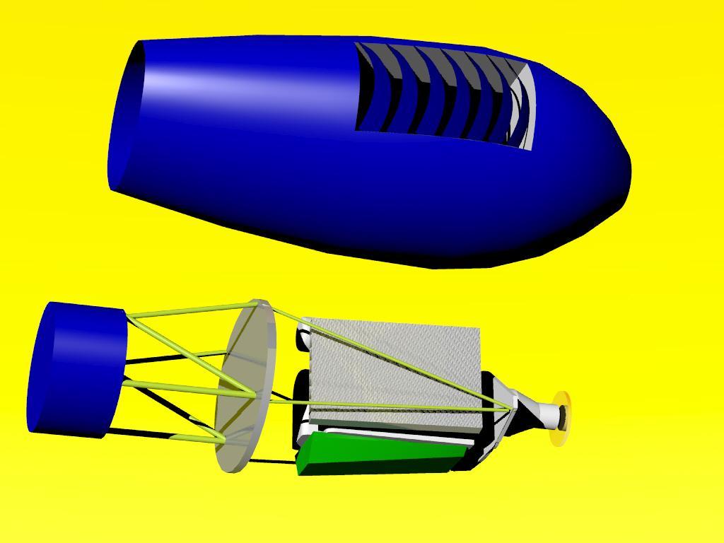
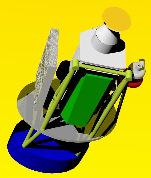
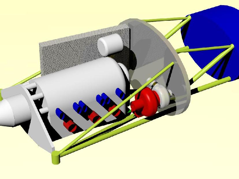
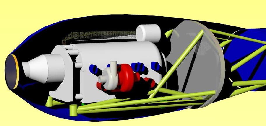
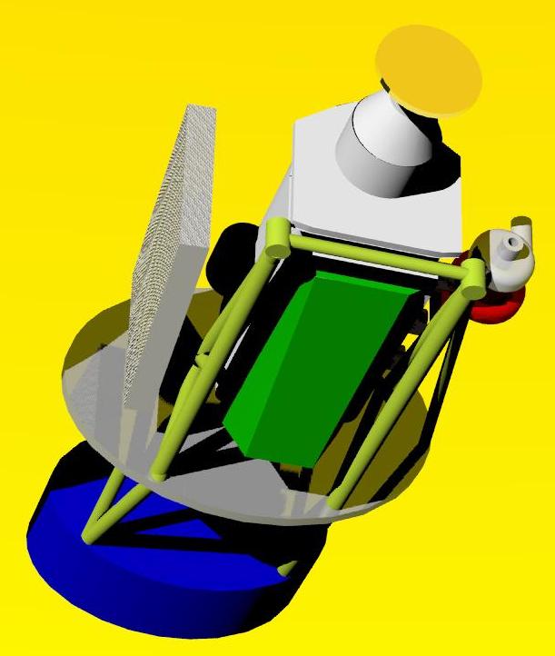
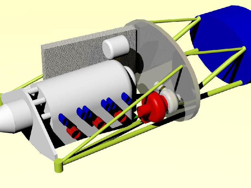
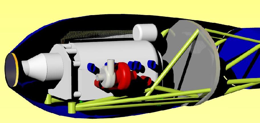
Well my engine and the mounting frame are now on a wooden jig so I can
finalize placement of the water pump and alternator, turbo charger and
possible turbo-compound. By playing with numerous pieces of foam and
engine placements I found that for best CG advantages for the SeaWind
with minimal flat plate area I need to move the heat exchangers as far
forward as possible.
Looks like your advice is half right Paul but to have a slim cowl I
needed a dynofocal engine mount and a dry sump pump.
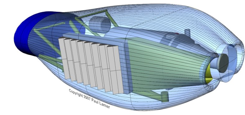
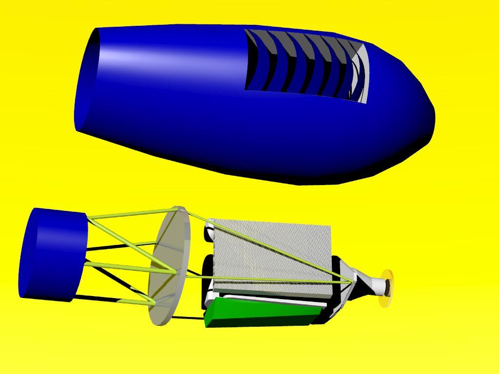
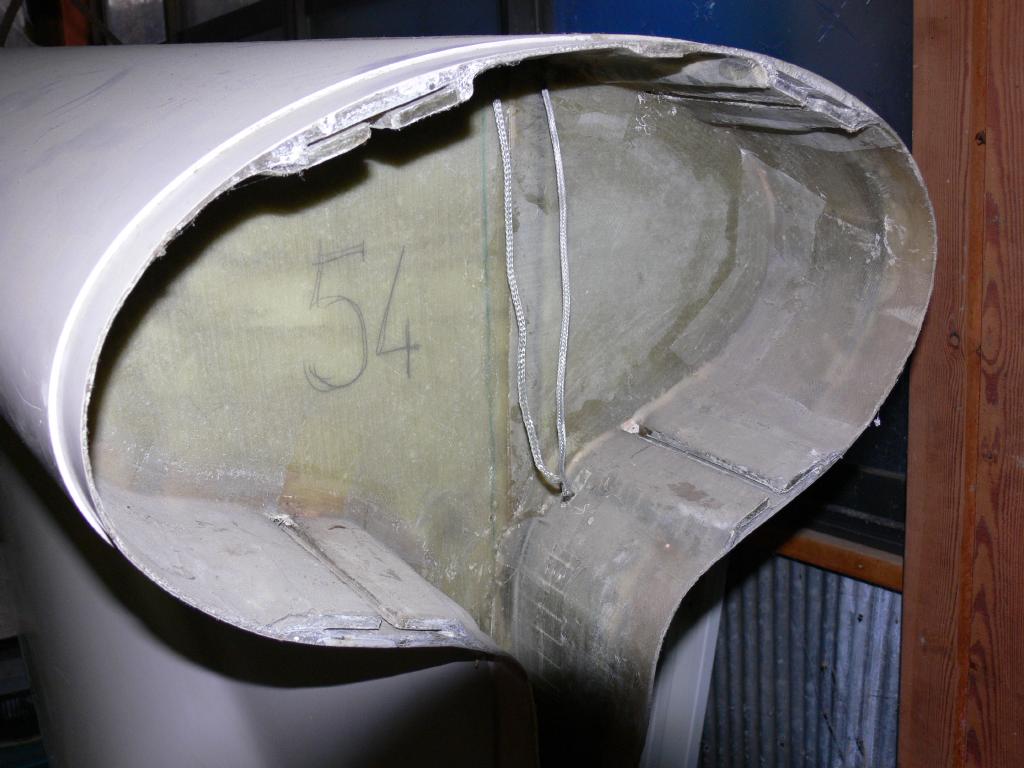
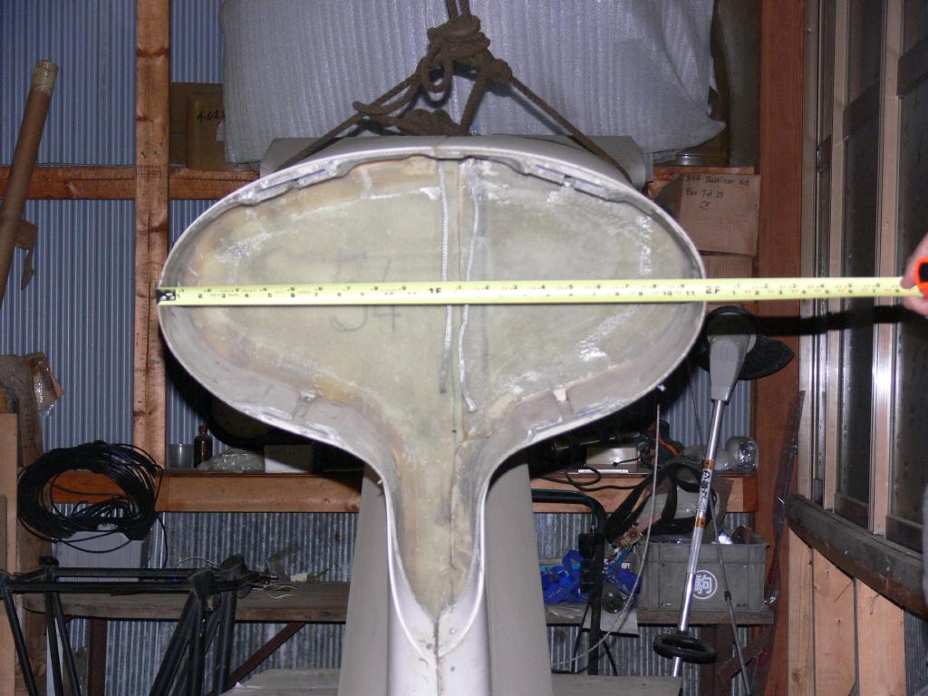
The result is a reverse flow U-shape water heat exchanger under the
engine.
Interestingly enough the cool side is not large enough for the needed
water heat exchanger like you have shown in illustrations but it is a
perfect space for a tilt down (access to the plugs) oil cooler fed by a
starboard nostril. Flexible oil lines and design care make it possible.
Air inlets ducting can be optimized and outlets for both heat exchanger
exhaust directly to low pressure areas outside the cowl. LOW COOLING
DRAG. Two cowl flap levers but that is fine with me. Top inlet like
you drew for me once is for the intercooler and it exhausts out the top.
Hot air from inside the cowl exits around the exhaust pipe outlet oval
hole.
I dropped the supercharger idea with this test engine because of a better
understanding of the blow down turbine size needed to overcome its the
supercharger requirements plus gain a significant power input. I will
retain a large turbo charger with the compressor facing forward for
normalizing at 18k critical. This will be ram fed through the port
nostril.
I'll keep the supercharger for testing though and eventually use the
traction drive for a turbo-compounding trials if bench testing
indicates enough power can be grabbed from a reasonable sized turbine
without slowing it down and melting it. More on this subject later.
Great Christmas present. With the CG advantages I can mount the starter
battery up in the engine mount frame and save 15 feet and many pounds of
large heavy cabling runs.Still room for a few cases of beer as well:)
Doug in Japan
Doug,
The Fluidyne air/oil cooler is on the port side. The core area for that
one is 9.5" x 11" x 3". The one mounted on the firewall is an oil/water
cooler. I don't have the core dimensions handy, but I would guess them to
be approx 6" x 12" x 2". Since I replaced the defective oil/air cooler
with
the Modine unit, which is working very well, I have disconnected and plan
on removing the oil/water exchanger.
Mark S.
Mark,
Thanks. So your total [oil] is about 313cu. inches, I'm guessing your max
power is 280Hp and so your hp to cooling ratio is about 1.1: 1 or
similar to Dave Leonards. That is good news. I am ball parking
400 cubic inches with 310hp. Thanks again and Merry Christmas to all.
Doug in Japan
---
Mark,
I figured it out as I see you mentioned core area. The Fluidyne model
number is DB-30617 and can be ordered in a dual pass with or single
pass like yours I believe,
One place that sells them is here.
http://www.customcarscentral.com/fludb30616-universal-all-makes.html
Cheers
Doug in Japan
Doug,
Yes, the dimensions given were for the core. I think you can also get them
from Summit Racing.
Mark
Mark,
I'll order the oil cooler after the New Years.
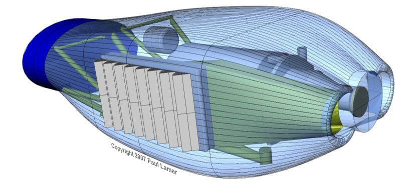
Now I am on to finalizing the water heat exchanger. What size radiator
did you use? In my research I found that C&R makes a great line of
custom radiators. One row type thickness is 37mm or 1.45" thick. Two
rows are 57mm thick or 2.2" inches. I pretty much realized that to get
the cooling I need and to maximize the frontal area on the heat
exchanger I will have to go under the engine like Paul has shown in his
book. However to get the performance in my relatively narrow cowl I
will have to go with a cross counter flow unit.
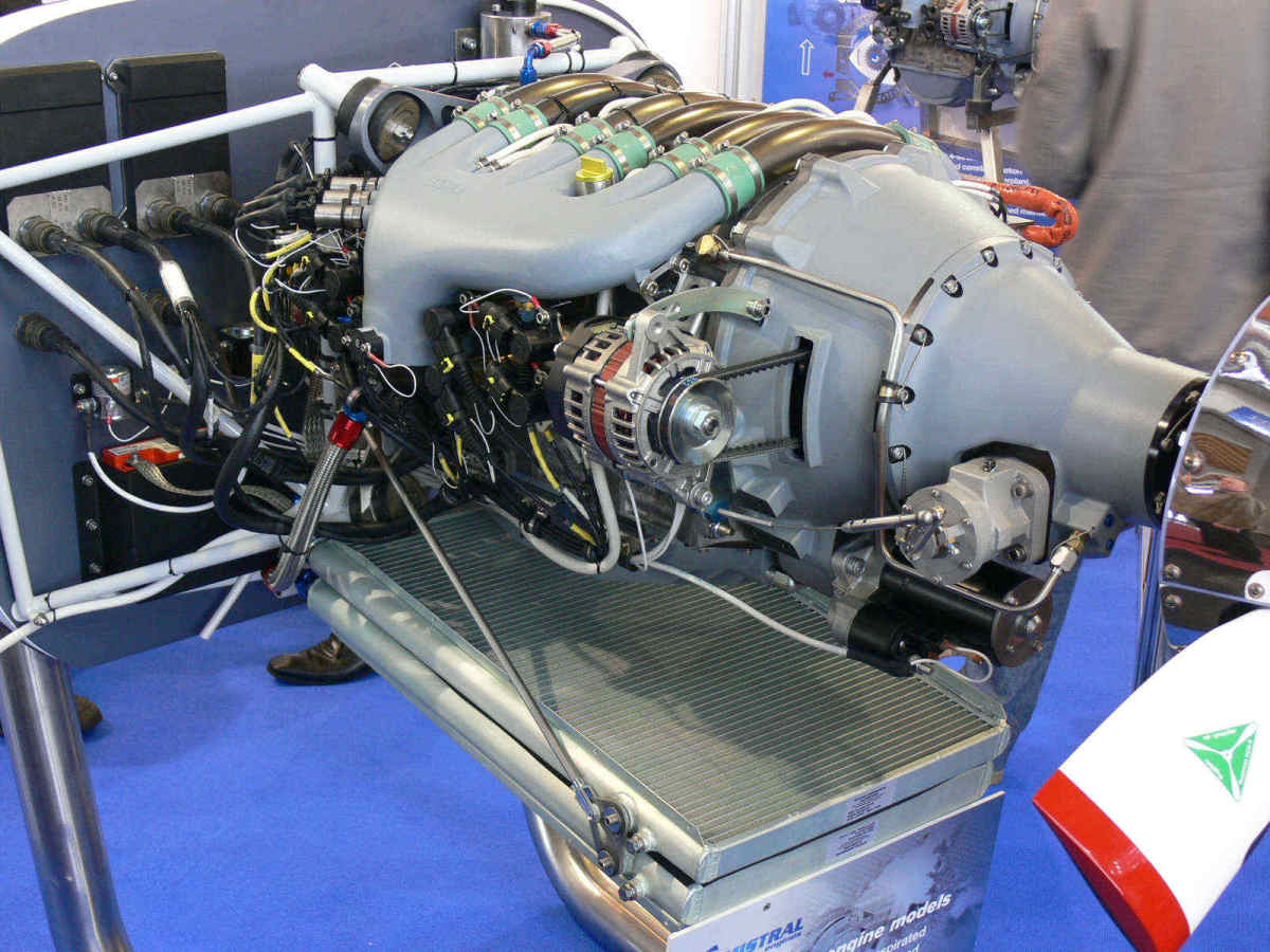
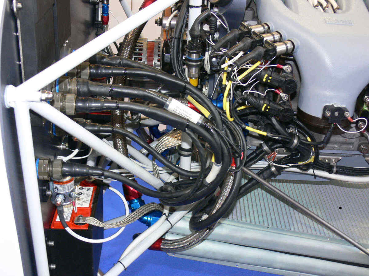
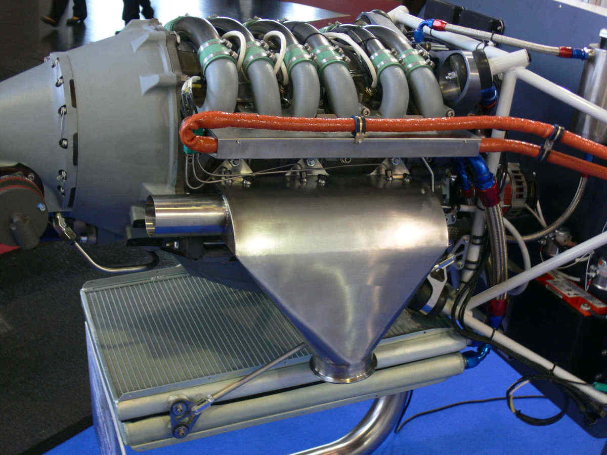
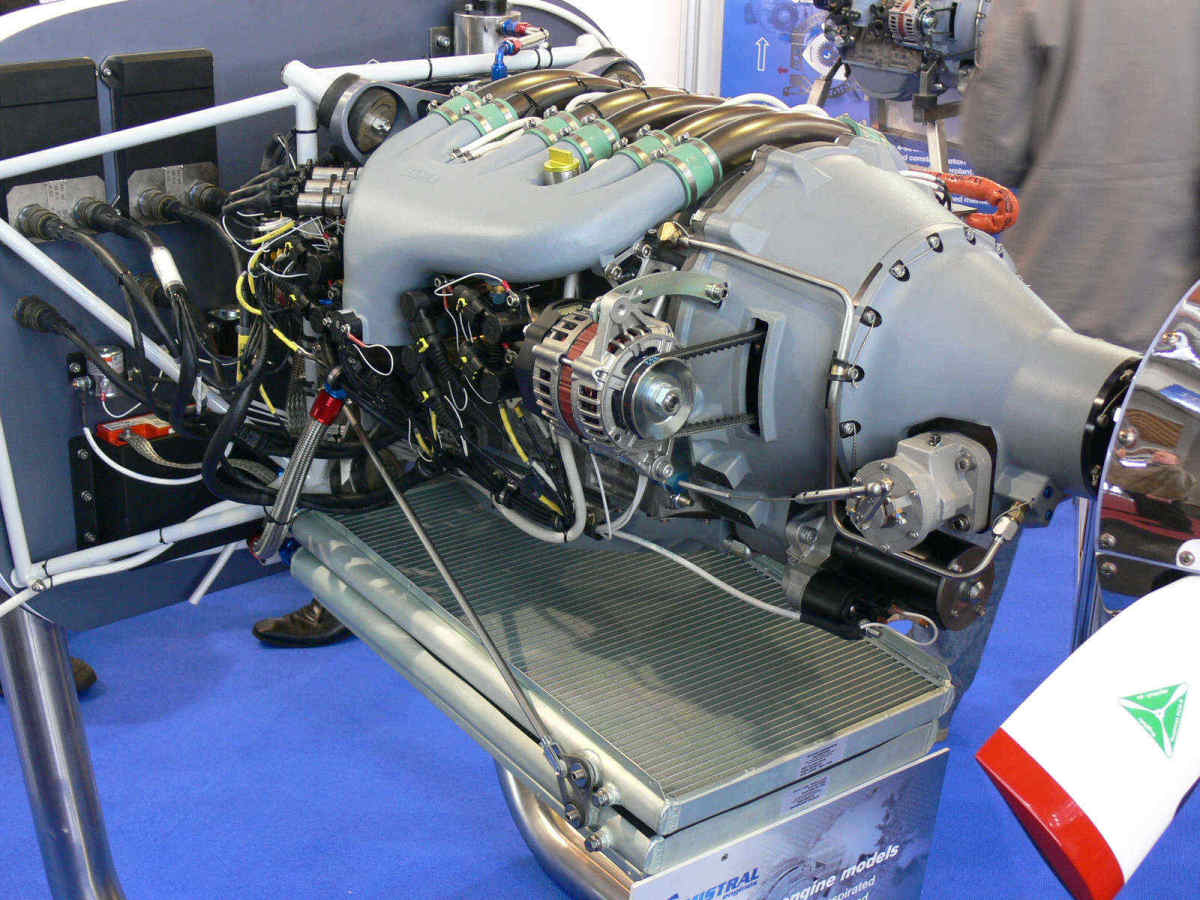
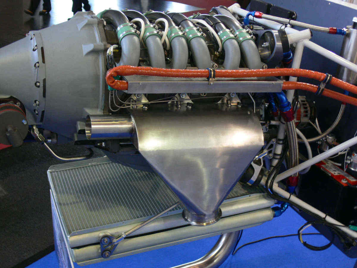
Mistral layout is sweet but I am not entirely sure what I am looking at.
Perhaps the bottom one is for oil? The flows go from side to side.
Paul can you enlighten us here?
Preliminary calculations with my present tight cowl shows I can fit 19"
wide by 18" deep cores with another 2.5 inches added for the tanks. If
it will be a counter flow design and each core is 1.45" thick, then
effective core thickness is 2.9". Total is 991 cubic inches Too much?
Doug in Japan
Yes the bottom one was oil but this is not a good way of doing it as
the one that gets the hot air from the other must be larger.
Temperature difference is everything. One degree F in air temp is a 1%
change in cooling. You have a long cowling so I would put at least
one heat exchanger on the cool side of the engine.
Paul Lamar
--
The Rotary Engine NewsLetter. Powered by Linux.
ACRE NL web site.
http://www.rotaryeng.net
Youtube key word UTUBPLEASE
Copyright 1998-2009 All world wide rights reserved.