So we want light weight side housings but also a tough wear surface,
right? Can we band saw all but about 1/4" of the factory iron side
housings away, and then use most of the Racing Beat aluminum housing
mated to it? What kind of gasket or seal would be required between
the iron and aluminum?
Happy New Year!
Matt-
I have been doing that for my single rotor work since about 10years ago.
The
prove of principle engine is still running strong with this arrangement.
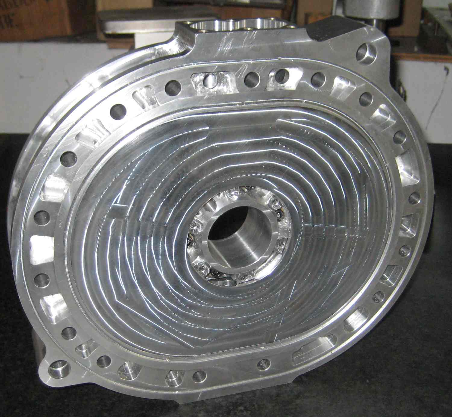
The problem area I encountered is around the stationary gear area whrere
the
CI and AL need to be connected (first picture). It was only possible with a
lot of JB Weld, in a way I would not want to have in a flying engine.
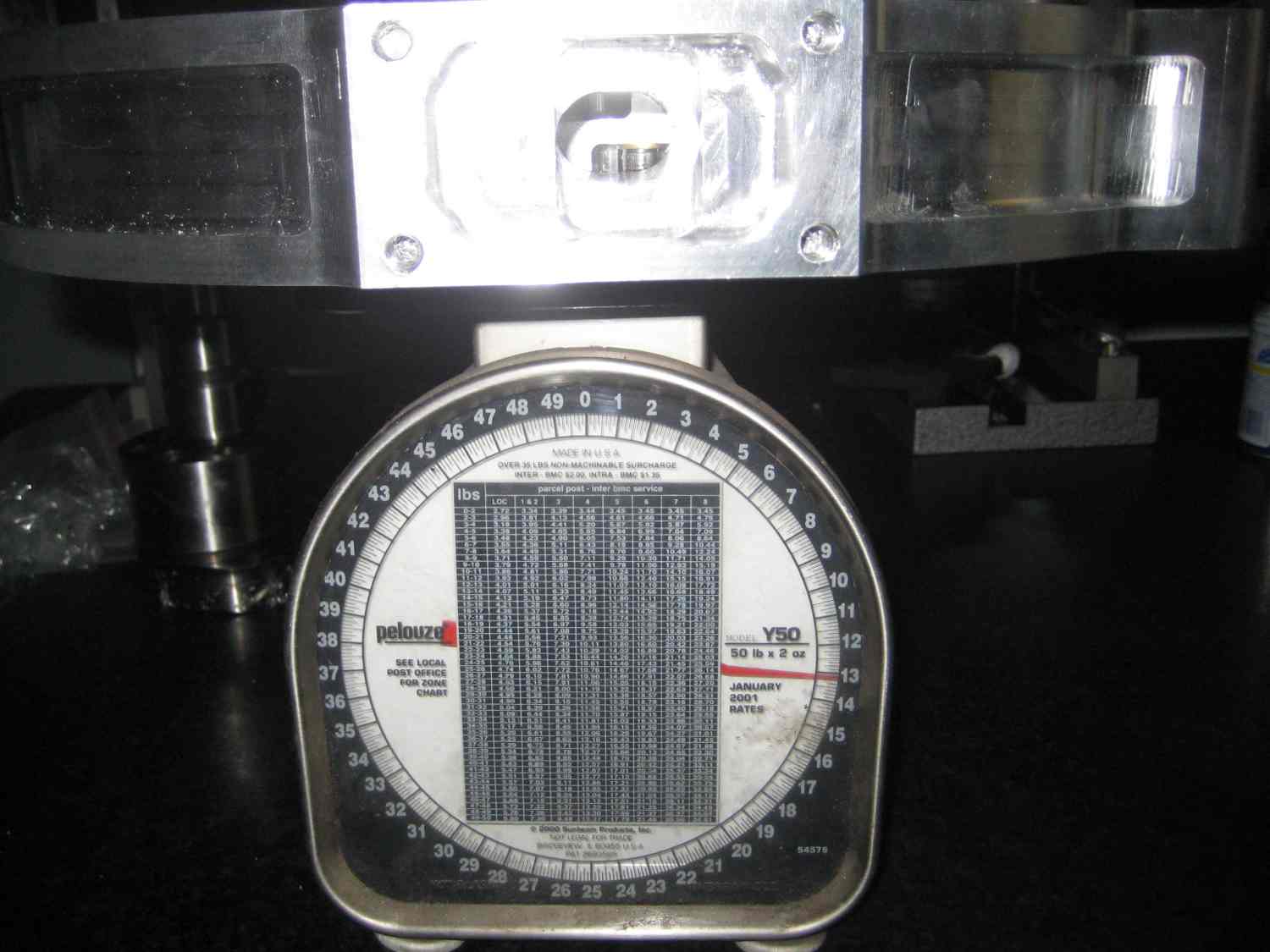
The flying engine side housing has a CI running surface insert(second
picture).
I do not have a design for the center housing nor for a power-take-off side
housing.
Happy and prosperous New Year.
Richard Sohn
N2071U
Matt, It is possible to design a two piece housing in CAD which makes open
casting patterns, or CNC parts since no core pattern is needed. The only
chalanging part is keeping the water amd oil separated at the stationary
gear/main bearing area. There is room for "O" ring seals (actually 2 seals)
and the clamping force can be the bolts thru the stationary gear threaded
into the rotor face side. The bolts can have intermediate bolts added to
double up the number. The center housing has no stationary gear or bolts and
needs a different approach. I have designed it with one side fitting into
the other like a piston in an air cylinder with radial "O" rings. In all
housings the outer edge is sealed by "O" rings which follow the shape of the
parts around the ports. Originally I intended to use nickel iron wear
surfaces and magnesium for the remainder of the housing. I was tying to
avoid detonation gun coating of the aluminum wear surface. Furthur research
indicates that a high silicon content aluminum alloy designed for automotive
pistons mau surve as its own wear surface. I am looking at 398 alloy with 17
%silicon. Remember the vega that chevrolet built or briggs and stratton lawn
mower engines. These engines have more oiling due to splash than the rotary
apex seals and will require 2 stroke oil in the fuel for the apex seals as
is current practice. IMHO all the side seals which contact the aluminum
side housings are either running in oil from the flodded rotor or are
exposed to the same fuel/oil mix as the apex seals. The aluminum housings
can be furthur lightened by eliminating the porting and using a periphial
port arangement. Personally I have drastically redesigned the ports to get
away from the relatively sharp entry into the rotor housing, and added two
more ports in the center housing for a total of 8 for a two rotor engine.
The aluminum side housings will likely be less efficient than the iron
housings due to their ability to conduct heat away faster than an iron
housing. This will also influence heat load on the water side of the cooling
system. If you can tolerate the weight the iron facings seem to be the best
arrangement. Paul has posted renderings of this on the newsletter. My take
on it is that it can't be a thin flat plate because the stationary gear
bolts need something to thread into to clamp the centers together. You could
mount iron housings to the faceplate of a lathe and turn off most of the
housing leaving a raised center area which contains the stationary gear
bolts. Personally I would leave the entire face intact including dowel pin
and tension bolt holes etc to ensure the gear and bearing are properly
located. I realize this is not the insert wear plate others are using which
is lighter. Also getting one of those slick PSRU plate/motor mount plates
from Jeff will take the prop torque off the engine case which has resulted
in cracking around the dowel pins on some modified housings. This torque is
2.85 times engine torque due to the gearbox. That leaves only reaction
torque from the accessory end rotor on the dowel pins.If you could
adequately protect the running surface of your doner housing you might avoid
having to lapp the part, or at least reduce the price. If you intend to lapp
the parts anyway then reject housings (warped or worn) should be
available, however these parts are all nitrided since 1994, and some before
that, and would need retreatment of the surface. It would require two center
housings to make parts which can nest into one another for a radial "O" ring
seal in the center.The available weight reduction doesn't seem to merrit the
cost and complexity for the center housing. Most interest is for a light
weight one rotor which doesn't have a center housing and there are still
two bearing mounts to clamp the center area together even if the gear is
turned off one of them. There are also some other aluminum alloys which may
need no surface treatment. The first one I found was used by BMW and had
zirconium in it. This alloy has to be pressure cast where the 398 can be
gravity cast. Someone needed my computer more than me so I lost my CAD
software last year and my project is delayed. I started this month to
recreate the whole thing in Rhino which I had on an ancient hard drive. It
took forever to get the shetches part of the drawings done in autocad14
separated from the 3D solids and imported into Rhino. I did most of a
dunafocal engine mount front housing yesterday and as I try to remember how
to work Rhino the speed will increase eventually. When I get done in a few
months The solid models will be available free to anyone, with stl models, G
code etc included. I am doing cast parts but the G-code of finished parts
would permit CNC machining directly from billets.
george grimes
George, you need paragraphs :)
Paul Lamar
Matt and George
kinda like this
jeff
--
The Rotary Engine NewsLetter. Powered by Linux.
ACRE NL web site.
http://www.rotaryeng.net
Youtube key word UTUBPLEASE
Copyright 1998-2009 All world wide rights reserved.