Paul
Happy New Years
George brought up a point recently about reacted torque. Has there been a
discussion in the past eight years that I missed on this subject?
Should this a concern when designing our motor mounts as related to
fractured housings caused by the dowel pins twisting?
I know you have been promoting motor mounts that bring the increased
prop torque directly through the rear housing as the reactive forces
have a direct path to the motor mounts without having to twist the whole
engine. I agree this is one of the best ways to do it. However to keep
a slim cowl (under 22" wide and slip a 19" heat exchanger in there as
well I have to design a different bed mount.
I can modify the existint mount and extend the lower tubes forward but
only enough to catch a motor mount near the intermediate housing.
Sooo ... to strengthen the engine against torque and come up with a
usable motor mount I am considering using a LeMans 26B approach for the
13B. This would be a thick aluminum spacer plate with ears extending
out (sort of like Tracys) and a thicker oil pan welded to the center
section The ears would be the at mid section only and catch the main
Barry mounts. The accessory side would need bushings that could handle
the approximate 75lbs of upward force.
Any thoughts on this?
Doug in Japan
I don't know whether you missed it or not. Apparently you did.
It all has to due with shortening the load path.
The motor mount must react the total torque the drive train
is generating and the vertical loads in a high G landing or
pull up. I'll use the term drive train because the system
in a car is the same as it is in an aircraft engine with
a gear box. If the engine is generating 200 foot pounds of torque
and that is fed into a 2.85:1 gear box then the total torque
the motor mounts will see is 570 foot pounds.
Early RX7 12A engines
used a motor plate bolted to the front cover to react this torque.
Mazda soon realized their mistake and moved the motor mounts back
to the center housing on the 2nd gen as the torque of the engine
increased. The 280HP 3rd gen had the mount even closer to the gear
box on the aft housing.
Then what happened next is the aft housing
started failing around the dowel pin as the dowel pins were
designed to feed the torque from the front rotor to the center
housing and then into rear rotor and thence to the gear box.
The motor mount on the other hand had to deal with the total torque
out of the gear box in the half a dozen hundred foot pound range.
Ideally the best place for a motor mount is on the gear box so the
high torque numbers do not have to go through the bell housing.
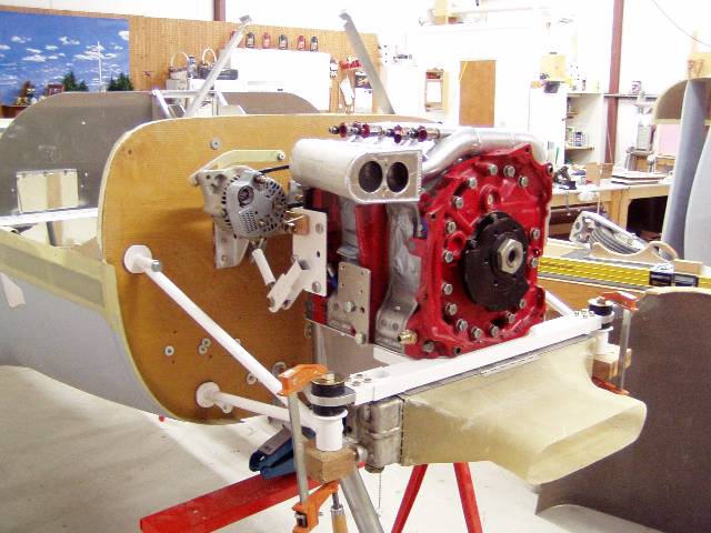
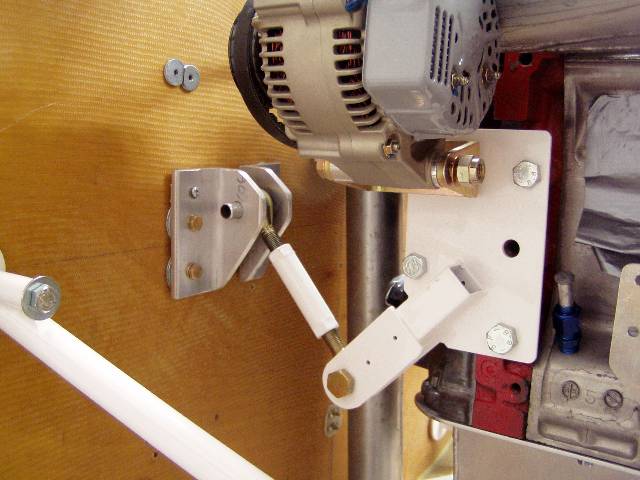
Years ago we came up with the motor plate idea that reacted the
600 foot pound prop torque directly. This relieved Tracy's spacers
from that onerous job. Unfortunately these motor plate things were
too expensive for people so they were not adopted except for
one or two people. Bob white was one and he tested the scheme
in a crash. Nothing to due with the motor plate but it largely
survived.
In the mean time Mistral went back to the early RX7 scheme where
the prop torque was reacted all the way through the engine
to the front cover so they could bolt the engine into a Lycoming
dynafocal type mount. Therefor both the Mistral engine and the
Lycoming block had to be beefed us to handle prop torque. This
added a bit of weight. The shortest load path gives the least
amount of weight. A F8F Bearcat motor mount is bolted to the spar
for that reason. Continental on the other hand used a bed mount
which was an improvement for light aircraft.
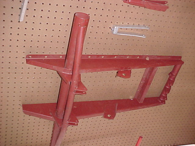
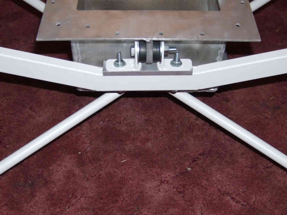
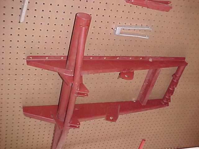
Then along came Jim Griswald designer of the Questair Venture.
He improved the Continental bed mount further by moving just two motor
mounts further forward under the engine CG. Very similar to a Mazda
3rd gen scheme. That is what I copied with the early schertz beam
and Bill Schertez refined. Another advantage is the vertical
engine reaction loads go directly into the rubber bushings in a hard
landing or high G pull up. "For every action there is a reaction."
Newton.
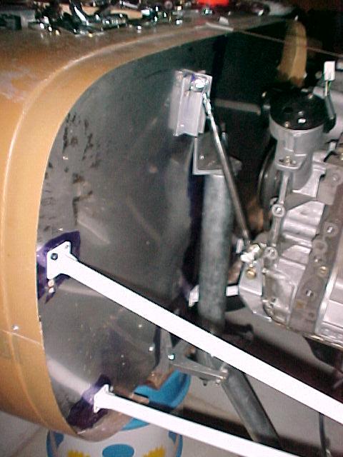
Along came Jeff Doddridge that lowered his NC shop overhead to the point
he could sell motor plate mounts at a much lower price so we switched
back to that ideal configuration. Yes they require longer motor
mount tubes but that adds very little weight and is easy to do.
Much easier than coming with a with a front cover to hang
the engine off of.
Also re-read
http://www.rotaryeng.net/mm-instruct.html
Paul Lamar
Paul,
Thanks. That was a very informative narration and confirmed a few hunches
I had. I was thrown over the years by some conflicting advise on your
web page. For instance. "The ideal motor mount brackets would be cast
into the Mazda front cover to fit a Lycoming dynafocal mount. That is
available from Mistral if you are able to buy one of their engines."
This may be ideal as in 'easy to mount to an existing motor mount' but
according to information about reacted torque and bending forces while
in flight operation, it is not optimal for unreinforced Mazda rotary
engines. The last phrase is key. I can't claim to know what
reinforcement Mistral put into their engines but it is a good bet the
robust cast oil pan wasn't made just to look pretty. Their through
bolt interfaces and dowel pins reinforcement were probably well thought
out also. The conical PSRU obviously transmits torque to the rear
housing in the most efficient manner. It is interesting to note that
the 800 hp 13B dragsters are probably transmitting less torque to the
housings than a airplane equipped with a 2.85 or above PSRU.
The Venture bed mount system as introduced is another good idea you
introduced. Does this imply it would be a good idea to copy this design
for the rotary? In other words would a stiff chrome molly angle frame
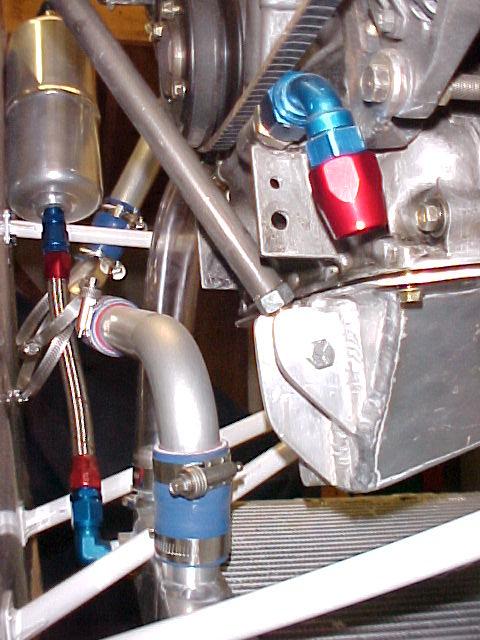
connecting to all the oil pan bolts prevent engine twist? In my opinion
it would not without increasing the size of bolt. The present oil pan
housing threads will see increased loads beyond their design function
which is to compress a sealing gasket on a relatively lightweight
unloaded object.
Over the years is seemed to me that most of the discussion was concerned
with designing the motor mounts to withstand six g landings and pull
ups. Perhaps the reacted torque issue is the more important one to be
concerned with. We have to qualify the term "ideal mount" though.
For use with Tracy's PSRU it would be a CNC mount plate as Jeff has made
though you have to admit the right angle interface of the PSRU and
mounting plate is not ideal. It may however be adequate. The "ideal
PSRU" is something in the nature Mistral designed while the "ideal
motor mount" might be a bed mount with two of the legs catching
Mistral's integrated bell housing/gearbox and the two farther back on
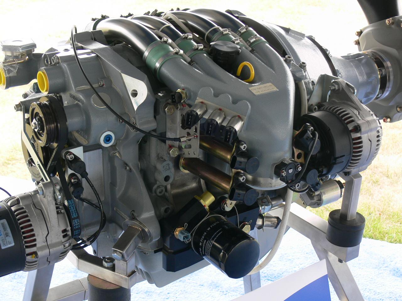
the engine somewhere. Ironically this might look a little bit like the
static display used in air shows.
Doug in Japan
The vertical load amounts to 1800 pounds in a hard landing
so it should be considered important.
Only three mounts are necessary and that is why the Questair
rear mount is so rudimentary. The two front mounts can take all
the torque and 90% of the vertical load.
Paul Lamar
--
The Rotary Engine NewsLetter. Powered by Linux.
ACRE NL web site.
http://www.rotaryeng.net
Youtube key word UTUBPLEASE
Copyright 1998-2009 All world wide rights reserved.