On another note: Being a complete computer and electronic nerd, you showed a
single lobe trigger wheel on one posting and some instructions I have says I
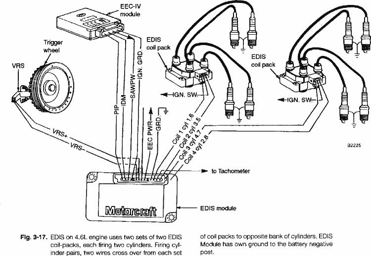
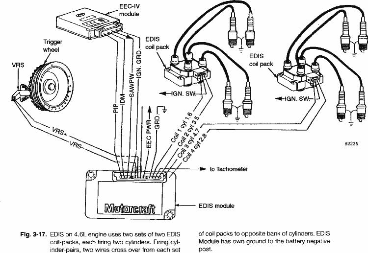
need a 36 tooth trigger (reluctor wheel). The EDIS system diagram I coppied
shows one EDIS module firing two four spark plug coils with one VR
pickup plus an EEC-IV module and and the other instruction says I need two
EDIS controllers, two VR pickups (20 and 27% BTDC) and a four coil pack. The
Ford four spark plug wire coils, I have, appear to have two coils and I also
have the four coils that came with my Renesis engine.
Could you post a simple schematic for both of these ingnition systems, or if
you already have, give me the approximate dates and I will search my unread
files. Also, how to find TDC. (I think there was a post about an apex at the
oil injector holes)
Karibian
The best way to find top dead center is make a hose barb
fitting out of a spark plug and fill a plastic tube
and the chamber with ATF. Rock the e-shaft back and fourth
until the ATF in the tube is at its peak. That is TDC.
Ford EDIS ignition controllers will work without computer
input, set for 10 degrees of advance. It just needs a
power source and input from a vr sensor. In normal
operation, the computer sends a correction signal
that the controller uses to change the spark advance.
One EDIS would be set to control the leading plugs
with a wasted spark, and the second would control the trailing.
The EDIS system requires a 36-1 wheel (36 teeth with 1 missing).
You can test the vr sensor and timing wheel by chucking
the wheel in a drill press and jigging the sensor next
to it. Attach an o-scope to the sensor output. You'll
also be able to tell what the tolerances are on the
spacing between the vr and the wheel.
Make folders and drag these messages into the folders.
Paul Lamar
--
The Rotary Engine NewsLetter. Powered by Linux.
ACRE NL web site.
http://www.rotaryeng.net
Youtube key word UTUBPLEASE
Copyright 1998-2009 All world wide rights reserved.