On another note: Being a complete computer and electronic nerd, you showed
a
single lobe trigger wheel on one posting and some instructions I have says
I
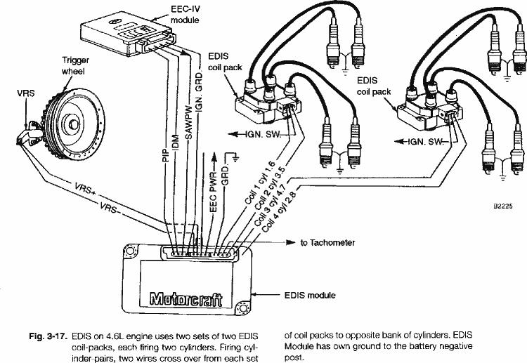
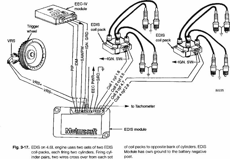
need a 36 tooth trigger (reluctor wheel). The EDIS system diagram I coppied
shows one EDIS module firing two four spark plug coils with one VR
pickup plus an EEC-IV module and and the other instruction says I need two
EDIS controllers, two VR pickups (20 and 27% BTDC) and a four coil pack.
The
Ford four spark plug wire coils, I have, appear to have two coils and I
also
have the four coils that came with my Renesis engine.
Could you post a simple schematic for both of these ingnition systems, or
if
you already have, give me the approximate dates and I will search my unread
files. Also, how to find TDC. (I think there was a post about an apex at
the
oil injector holes)
Karibian
The best way to find top dead center is make a hose barb
fitting out of a spark plug and fill a plastic tube
and the chamber with ATF. Rock the e-shaft back and fourth
until the ATF in the tube is at its peak. That is TDC.
Ford EDIS ignition controllers will work without computer
input, set for 10 degrees of advance. It just needs a
power source and input from a vr sensor. In normal
operation, the computer sends a correction signal
that the controller uses to change the spark advance.
One EDIS would be set to control the leading plugs
with a wasted spark, and the second would control the trailing.
The EDIS system requires a 36-1 wheel (36 teeth with 1 missing).
You can test the vr sensor and timing wheel by chucking
the wheel in a drill press and jigging the sensor next
to it. Attach an o-scope to the sensor output. You'll
also be able to tell what the tolerances are on the
spacing between the vr and the wheel.
Make folders and drag these messages into the folders.
Paul Lamar
Karibian.
Systems with a toothed trigger wheel have one tooth omitted in
order to reset the internal counter once per revolution. After the missing
tooth passes it counts to a predetermined number of teeth and fires a plug,
then continues counting the same number of teeth to fire the next plug until
the reset tooth passes and starts another revolution. If it is connected to
the EEC IV computer, engine mounted sensors determine fuel injection pulse
width and optimum ignition timing. The computer sends a SAW (spark angle
width) which decreases the number of teeth as well as the fractional part
of a tooth counted for the first plug after the reset tooth. The rest of the
plugs fire at the tooth count after the first plug firing point. To run a
fixed timing the computer adds no functionality since the EDIS runs at 10
degrees advance without the computer.
The actual fixed advance is determined
by the mounting position of the VR sensor (teeth behind the missing tooth).
IMHO firing both plugs on a rotor using the wasted spark side of the coil
would be a mistake. The EDIS accumulates a fixed charge which is discharged
through the coil. You might think of this as the condensor on a points type
ignition. The intent is to fire one plug of a cylinder under compression and
one which is not. Firing two plugs both under compression requires more
voltage and might misfire at high RPM or result in overheating the coils
without cooling air directed over the coils.
The single tooth ignition calculates the percent of time required
of the time for a complete revolution to determine the spark events. This
would consist of several solid state timers and comparitors. A timing map
is usually incorporated for spark advance.
It is possible to have a VR sensor for each spark plug with it's own
coil on plug and no computer chips. This approach would
have fixed timing
and relies on a precision mounting of the VR sensors both in their relative
location and spacing from the trigger tooth as it passes. With this approach
a small amount of electronic components and a capacitor to fire the coil is
required for each plug since the VR sensor doesn't fire the coil directly.
george grimes
Let me see if I can simplify this.
The attached pdf is very clear on how it works.
"Inside the EDIS module is a microprocessor, VR sensor input, and coil
driver transistors. The VR sensor drives an input detector which fires
on the falling zero crossing of the [CAS trigger missing tooth] signal
at 300mv. The module then uses this information to calculate the current
crank position and speed [RPM]. When the EDIS module determines the
spark should be ignited, [front rotor back rotor] it fires the
appropriate coil."
IMHO If you use only one EDIS system and one pickup
and one coil pack and the unit is set to 4 cyl
you will get wasted spark I think. The four cyl setting is used
because a 2 rotor fires the same number of times per engine
rev as a 4 cyl piston engine. As George pointed out wasted
spark is a no no in a rotary.
However since each Ford coil has four spark outputs
and there are four trigger wires coming out of the EDIS
that support two coil packs choosing the right
outputs using two coil packs may not give
a wasted spark but you still have four plugs
to fire. It is too much on my little brain to
figure out if it can be done with just one coil
pack without wasted spark.
I think the firing order in a 4 cyl is 1 and 3 fire
together and 2 and 4 fire together. If 1 and 2 are fired
together one cyl will have wasted spark using only one
coil pack.
I could be wrong so I would set up on the bench
and see what happens.
Paul Lamar
--
The Rotary Engine NewsLetter. Powered by Linux.
ACRE NL web site.
http://www.rotaryeng.net
Youtube key word UTUBPLEASE
Copyright 1998-2009 All world wide rights reserved.