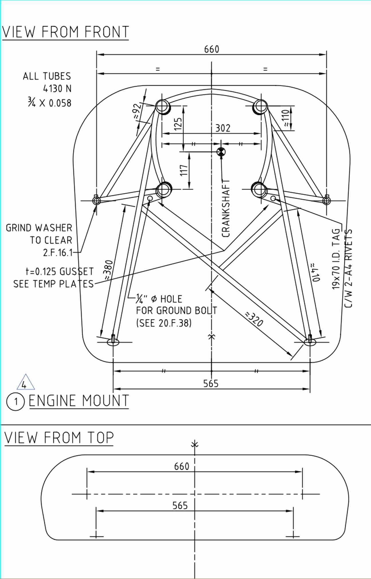
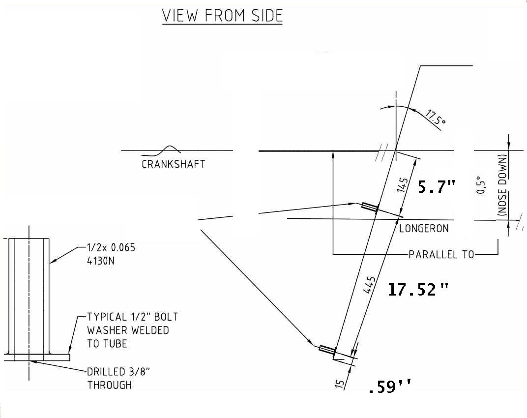
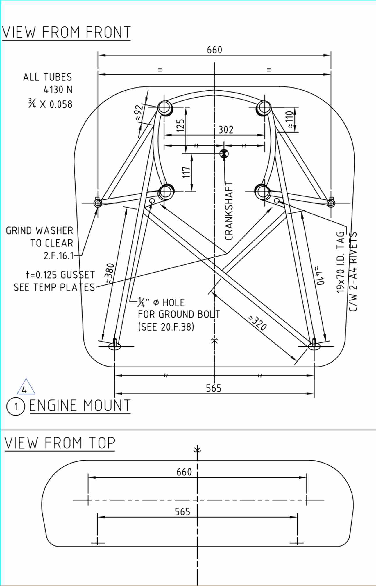
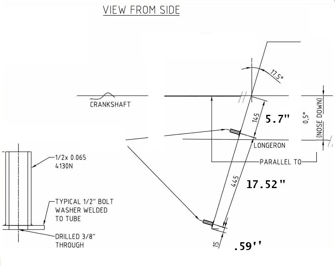
Paul, could you please render a new version of the CH-640 mount(based on the
ch-801, but with a lower rear attach from oil pan rear over the nose gear
strut), utilizing the Doddridge plate, Tracey Cook RD1-C, rear lower oil pan
vibration stabilizer, etc. (basically all the features of the final version
you sent) but move the plate and engine out 6" further from the fire wall to
accommodate for the use of the RB light weight center and end plates? I
spoke with Mathieu Heinz when I picked up the wings in Canada, discussed the
implications of the lighter weight installation, and his recommendation was
to move everything out 6".
Also could you make notes for me as to the basic raw construction materials
used, like different tubing sizes, IE diameter and wall thickness. I have
both Q-Cad and Alibre now, so I should be able to read the cad dwgs
directly.
Craig Smith
snips...
Preliminary motor mount design.
One of the unanticipated (by me) side benefits of a light weight 200 pound
(with PSRU & acc.) 250 HP p-port all aluminum engine moved six inches
forward in the cowl is more room for the cooling system.
I would also take advantage of the increased net payload by enlarging the
fuel tanks for more range. Lots of range is a safety factor as you could get
somewhere and need to go back because of weather.
You will also need a 3 blade prop to absorb all this HP.
This airplane is going to blow a lot of peoples minds.
Excellent short field performance will be all too obvious.
Paul Lamar
Two hundred pounds with PRSU and acc. ? Is this accurate Paul, I thought
that was an approximate weight for the light single rotors.
John
Well the bare block two rotor came out to 109 pounds.
There is a picture of Doug holding one at 7 Stock on the front page of the
web site.
I guessed at the rest. 45 pounds PSRU. 7 pounds starter
8 pounds alt., etc., etc..
Poorly educated guess :) Probably not including fluids.
------------------------------------------------------
Craig,
What do you think about bracing the cowl area with a couple of 1/2 inch 4130
tubes to feed rear motor mount loads back into the longerons under the gull
wing doors?
Just think of it as an extension to the motor mount.
Then I can use this top rear mount scheme.
----------------------------------
Update 640 specs etc.
Paul Lamar
The only bit of information that I can seem to figure out is different
between the 801 and the 640, but has to be implied from the drawings is that
according to dwg. 20-P-1, is the 640 firewall angle is 17.5 degrees, vs the
18.5 degrees of the
CH-801 according to the dwg. THRUST.
All other hard points and dimensions are identical. I'm making assumptions
about firewall details other than the motor mount points.
C. Smith
Send both dwg's and I'll have a look.
Paul Lamar
I just called them and they said they use the same O-360 motor mount on both
the 801 and the 640. That means the firewall angle is the same. They also
have no objections to the reestablishing the fifth upper mount using the two
1/2 OD 4130 tubes.
I told them I would send 3D's if they send me email.
What is really neat about the 801 THRUST pdf is it shows the CG position of
the Lycoming engine. This is the best company to work with I have found so
far. Van's will not tell you anything :)
Paul Lamar
Well, I'm just going by what the drawings say. However, the drawings also
note that the tolerance is 5 degrees on the thrust line. Go figure. I've had
good luck with getting information, when you use the telephone, e-mail
sometimes gets "lost". When you do have their attention, there are no
secrets, unless there is pending litigation......
Do you recall who it was you were speaking to?
C. Smith
I did not get his name.
Apparently the only real difference is the width of the firewall.
The cowl will be much tighter.
Here are the corrected 3D's.
Paul Lamar
Craig Smith wrote:
Paul in light of the differing "official" responses, please look at the
scans for the dimensions
I think you got the wrong information. What is the width of the firewall you
were given, did you speak to someone in Canada? My firewall width is 920mm
by 818mm. tell me if the dimensions come through, and I'll bump up the
image.
C. Smith
Max firewall width is 800 mm on my dwg.
Your 920 mm hight number sounds about right for the flat
firewall. Projected height (front view) is the same as the width or about
800 mm. I scaled the width off of these dwgs.
Your buddy Mathieu sounds like our president :)
"I don't know anything about it but it is messy".
I don't think mechanical engineering skills are genetic.
The guy is a loose cannon. Imagine insulting your customers
and the people trying to help them (me).
I was very proud of myself for being so constrained.
Paul Lamar
The Rotary Engine NewsLetter. Powered by Linux.
ACRE NL web site.
http://www.rotaryeng.net
Youtube key word UTUBPLEASE
Copyright 1998-2009 All world wide rights reserved.