Paul, could you please render a new version of the CH-640
mount(based on the ch-801, but with a lower rear attach
from oil pan rear over the nose gear strut), utilizing the
Doddridge plate, Tracey Cook RD1-C, rear lower oil pan
vibration stabilizer, etc. (basically all the features of
the final version you sent) but move the plate and engine
out 6" further from the fire wall to accommodate for the
use of the RB light weight center and end plates? I spoke
with Mathieu Heinz when I picked up the wings in Canada,
discussed the implications of the lighter weight
installation, and his recommendation was to move everything
out 6".
Also could you make notes for me as to the basic
raw construction materials used, like different tubing
sizes, IE diameter and wall thickness. I have both Q-Cad
and Alibre now, so I should be able to read the cad dwgs
directly.
Craig Smith
snips...
Preliminary motor mount design.
One of the unanticipated (by me) side benefits of a light weight 200 pound
(with PSRU & acc.) 250 HP p-port all aluminum engine moved six inches
forward in the cowl is more room for the cooling system.
I would also take advantage of the increased net payload by enlarging
the fuel tanks for more range. Lots of range is a safety factor as
you could get somewhere and need to go back because of weather.
You will also need a 3 blade prop to absorb all this HP.
This airplane is going to blow a lot of peoples minds.
Excellent short field performance will be all too obvious.
Paul Lamar
snipss.
------------------------------------------------------
Craig,
What do you think about bracing the cowl area with a couple
of 1/2 inch 4130 tubes to feed rear motor mount loads
back into the longerons under the gull wing doors?
Just think of it as an extension to the motor mount.
Then I can use this top rear mount scheme.
----------------------------------
Update 640 specs etc.
Paul Lamar
I will be sending you 7 pages from the prints, including FW
and Fuselage diagrams. I'm not a qualified engineer, therefore
unable to determine if your alternate solution is safe. Once
you have a look at the prints, and can determine if the
structures are up to the task, I would have no objections
to another approach.
Soon as I get home, I'll get them out to you.
C. Smith
Could you forward these 3D's to your friend at Zenair and
ask them if they have any objections. Perhaps send me his
email address and I will do it.
Paul Lamar
I am currently considering options for a Mazda 13b lightweight
engine installation. these drawings represent one of 2 ways
to skin the cat. the significant modification I seek
comment on is the addition of the struts at the top
of the FW to transmit loads back down to the main spar.
Please review the included discussion. I look forward to
your comments, as to wheather this is a good idea, and or if you feel
any changes to improve it.
Craig Smith
CH-640 SN 00078
Craig,
This installation looks very messy at best and needs to be
redesigned in my opinion. However, with the drawings you emailed,
I can not offer a simple solution for you. The top tube going through
the firewall will damage the firewall as you will have a large
up/downward load in that area.
Mathieu Heintz
Zenair
What specifically is "messy" about it Mathieu?
At 100 FPS second take off/climb speed assume the net thrust from the prop
is 1000 pounds. To put that in HP perspective that would be 100,000
foot pounds second. Since one HP is 550 foot pound seconds that is
181 HP net out of the prop. Since the prop eff. is about 80%
that translates to 226 engine HP. Since max HP is a constant As speed
increases the net thrust from the prop decreases until the net thrust
equals the drag at top speed.
Given 1000 pounds of net thrust out of the prop the top MM strut takes half
or 500 pounds. The two lower rubber bushings take the other half.
error snips.............
--------------------------------------------------------------------
I forgot the down load introduced by the diagonal brace tubes.
I am so used to thinking of firewalls as being rock solid SS devices
braced by sheet metal cowling's over the instrument panel area.
This one appears to be free standing from the longerons up.
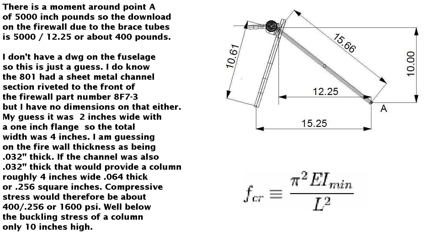
There is a moment around point A of 5000 inch pounds so the download
on the firewall due to the brace tubes is 5000 / 12.25 or about 400 pounds.
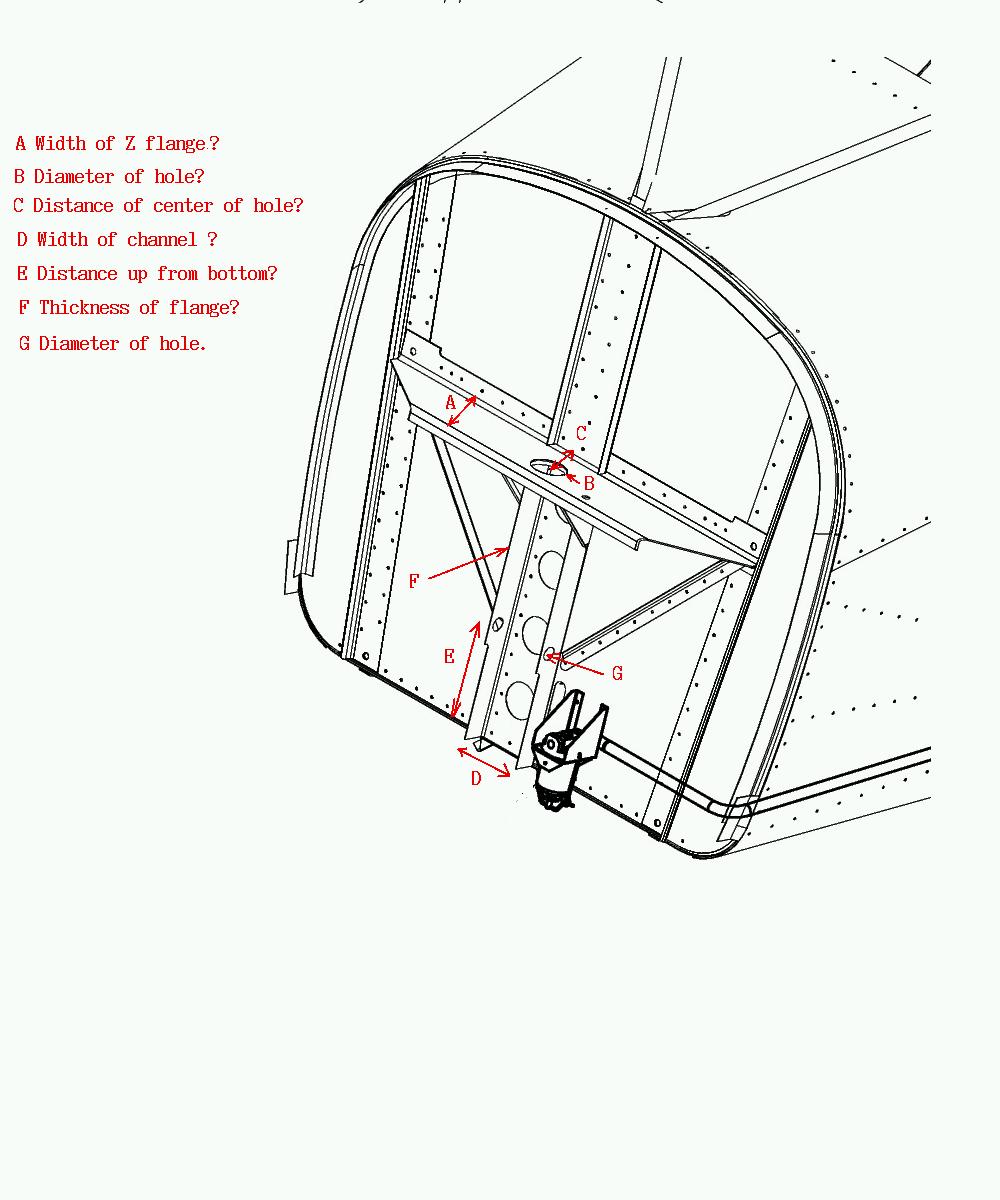
I don't have a dwg on the fuselage so this is just a guess. I do know
the 801 had a sheet metal channel section riveted to the front of
the firewall part number 8F7-3 but I have no dimensions on that either.
My guess it was 2 inches wide with a one inch flange so the total
width was 4 inches. I am also guessing on the fire wall thickness as being
.032" thick. If the channel was also .032" thick that would provide a column
roughly 4 inches wide .064 thick or .256 square inches. Compressive
stress would therefore be about 400/.256 or 1600 psi. Well below
the buckling stress of a column only 10 inches high. If it were
a 5/8 diameter 2024T3 tube with .035" inch wall it would
take 2500 pounds to buckle it.
The buckling formula is shown in the jpg for anybody that would
like to calculate the load the column will take.
E is ten million as I recall for aluminum and L is ten inches.
http://en.wikipedia.org/wiki/Column
I is a bit complicated to calculate but not impossible.
I would be helpful if we had some dimensions on this stuff.
Paul Lamar
Hi!
I sincerely dont want to critisize anyone´s work, and I may be mistaken. I am just voicing
a concern of mine that has come up from following this discussion.
This concern is that I have not been convinced that one specific compounded stress has
been taken into account in the calculations. Again, I have probably just missed something.
If so,
just ignore me!
Now, I have violated one of your fine drawings in MS paint, Paul. I indicated what I would
assume to be the C.G of the engine/prop combo. Probably not all that accurate, but I am
assuming that with anything other
than a heavy CS prop it will be behind the lower mounts.
Now assume a positive G pull out, no thrust, that will introduce a turning moment on the
engine twisting it backwards (G * force of gravity * L).
This will introduce a buckling load on the strut to the upper mount. This, in turn will
give rise to a compounded stress on the upper mounts of the motor mount (marked F in the
picture).
Now, one may not think this to be a significant factor but I think It could be. Under
limit positive loadfactor the weight alone gives near limit stress on the firewall.
introduce this extra stress and
the bolts could pop out.
I am under the impression that in the original design the the upper 3 points on the
firewall would be under tensile load and the lower 2 would be under buckling load.
In this case, the upper most is buckling, the middle two are tensile, and the lower two
are again buckling. This adds to the total stress on the firewall, concievably to a degree
for which it was not designed.
This still goes even if one decides not to use the upper most mounting point on the
firewall (infact, not using it is better than using it under buckling load).
So, what to do? Well, an easy way to reduce this twisting moment would be to move the top
mount forward. The moment will be reduced because dotted line A is shorter than ditto B.
The main issue still remains in
my mind though.
The only other option is to cross brace this "open" square in the space frame.
Oh, and has the redrive/lower engine mounting plate been designed for the bending it sees
from this turning moment?
Cheers!
Chris
I am glad to get in touch with you Chris. Finally some one that speaks
mechanical engineering.
Yes that is a factor. The CG of the prop/gear box/starter/all the engine
is behind the lower mount about 3 to 4 inches. Since the strut is already
experiencing tension load of up to 500 pounds due to thrust this moment
amounts to (3" X 250# X 6G)/12" (the distance from the lower mount pivot
point to the upper mount) = 375 # of compressive force. This cancels somewhat
the thrust tension load on the upper tube depending on the exact thrust.
The worst case scenario is no thrust 6G hard landing and in that case the
375 pounds would be the compressive load in the upper strut. Most certified
aircraft are designed for 4.5 G hard landing so perhaps the landing gear
may fail first. All our motor mount designs are all designed for this
6G worst case.
http://www.rotaryeng.net/mm-instruct.html
Entering this buckling chart for a .75 diameter .049 wall 4130 steel tube 25
inches long gives a maximum buckling compressive load of 4500 pounds.
That is over designed by a factor of 10 or so. Since the shank on the
rubber ball joints is 1/2 inch a 3/4 tube is called for.
I agree moving the strut mount 10 inches forward to the top of the plate
would reduce the wedging effect in a heavy landing at the expense
of reducing the max tube buc. load to 2500 # and the load on the
firewall/cowling.
The motor plate sees very little bending from this now as
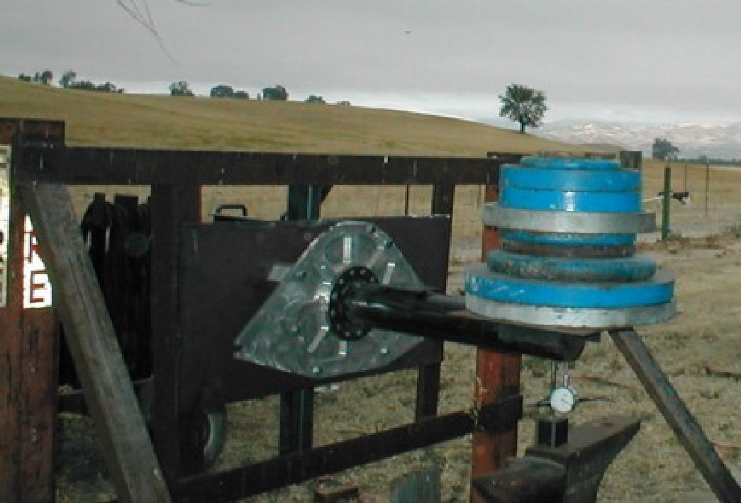
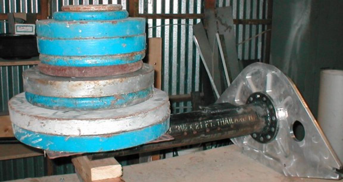
the pivot is rubber. It sees more bending from gyro torque reactions
on the gear box. We static tested the design for this and measured
the deflection. We also did some FEA's on the plate. One version survived
a crash that buckled the fuselage. The plate design has been around
for 11 years.
BTW I may be wrong about the 640 free standing firewall. Recent dwgs
sent to me by Craig indicate there is sheet metal riveted to the top of
the 640 cowl so no brace tubes may be necessary. That will reduce the
down load on the firewall. Perhaps a few sheet metal angle stiffeners
or a thicker skin will be needed on the cowl covering. The Plexiglas
windshield, if thick enough for bird strikes, will also had strength.
Paul Lamar
The Rotary Engine NewsLetter. Powered by Linux.
ACRE NL web site.
http://www.rotaryeng.net
Youtube key word UTUBPLEASE
Copyright 1998-2009 All world wide rights reserved.