snips..
I am currently considering options for a Mazda 13b lightweight
engine installation. these drawings represent one of 2 ways
to skin the cat. the significant modification I seek
comment on is the addition of the struts at the top
of the FW to transmit loads back down to the main spar.
Please review the included discussion. I look forward to
your comments, as to wheather this is a good idea, and or if you feel
any changes to improve it.
Craig Smith
CH-640 SN 00078
Craig,
This installation looks very messy at best and needs to be
redesigned in my opinion. However, with the drawings you emailed,
I can not offer a simple solution for you. The top tube going through
the firewall will damage the firewall as you will have a large
up/downward load in that area.
Mathieu Heintz
Zenair
What specifically is "messy" about it Mathieu?
At 100 FPS second take off/climb speed assume the net thrust from the
prop
is 1000 pounds. To put that in HP perspective that would be 100,000
foot pounds second. Since one HP is 550 foot pound seconds that is
181 HP net out of the prop. Since the prop eff. is about 80%
that translates to 226 engine HP. Since max HP is a constant As speed
increases the net thrust from the prop decreases until the net thrust
equals the drag at top speed.
Given 1000 pounds of net thrust out of the prop the top MM strut takes
half
or 500 pounds. The two lower rubber bushings take the other half.
error snips.............
--------------------------------------------------------------------
I forgot the down load introduced by the diagonal brace tubes.
I am so used to thinking of firewalls as being rock solid SS devices
braced by sheet metal cowling's over the instrument panel area.
This one appears to be free standing from the longerons up.
There is a moment around point A of 5000 inch pounds so the download
on the firewall due to the brace tubes is 5000 / 12.25 or about 400
pounds.
I don't have a dwg on the fuselage so this is just a guess. I do know
the 801 had a sheet metal channel section riveted to the front of
the firewall part number 8F7-3 but I have no dimensions on that either.
My guess it was 2 inches wide with a one inch flange so the total
width was 4 inches. I am also guessing on the fire wall thickness as
being
.032" thick. If the channel was also .032" thick that would provide a
column
roughly 4 inches wide .064 thick or .256 square inches. Compressive
stress would therefore be about 400/.256 or 1600 psi. Well below
the buckling stress of a column only 10 inches high. If it were
a 5/8 diameter 2024T3 tube with .035" inch wall it would
take 2500 pounds to buckle it.
The buckling formula is shown in the jpg for anybody that would
like to calculate the load the column will take.
E is ten million as I recall for aluminum and L is ten inches.
http://en.wikipedia.org/wiki/Column
I is a bit complicated to calculate but not impossible.
I would be helpful if we had some dimensions on this stuff.
Paul Lamar
So, what your saying is with the addition of the 801 specific parts to
the
firewall, it might very well be a viable design. I guess we would need
the
help of one of our 801 builders to identify the differences in the parts
and
reinforcements.
Paul, are the advantages of the top mount strut brace significant enough
over the lower brace to the nose gear bracket to warrent the effort?
Sounds
like a bigger mod than we first thought.
Why not try bouncing the original method off Mathieu?
C. Smith
I would not bother. I have seen his of attitude before. Rather
than suggest improvements he just bad mouths the entire project.
He obviously knows nothing about rotary engines. I think it is an
ideal rear mount as it is the simplest and lightest and half the thrust
is removed from the lower rubber mounts which are not all that
good in the radial direction anyway. I got the idea from Steve Beckham
and Everett Hatch as they used to mount their rotaries that way 15
years ago. They had to beef up the RV firewalls as well. Since the
engine is six inches further forward the old 801 bottom mount will not
work well.
I have a shear and a brake so when you get the firewall send
me a picture and I will bend up a reinforcing hat section and send
it to you.
Paul Lamar
Very well, I will take some photographs as soon as I can and forward them
to you. the firewall pan itself is in my hangar. I can't say I fully
understand all this, but the point about the longer distance changeing
the
effectiveness of the other system makes some sense. Do you need any more
structural detail from the prints, or has what I have sent enough for
your
needs?
I'm sorry about the conflict, too bad there couldn't have been more
constructive comment. I'm sure that when this aircraft shows up in OSH
and
Sun-N-Fun, we will hear a different song.
C. Smith
One high performance take off and they will come with hat in hand :)
This dwg is good. I think I have enough.
Is the firewall pan galvanized steel? If so that helps as E is 3 times
aluminum.
Paul Lamar
Let me know what dimensions you need, I'll measure them. I've got a handful
of suggestions to help the 801 mount fit a little better too.
I've been installing the connecting arm to the top-center mount point, and
had to fabricate a different mount attach to the center section to provide
clearance between the arm and the top of the renesis front section, among
other things. I'll send photos.
--Kenny A.
http://websites.expercraft.com/kennya/
I think we have it covered by now Kenny.
Thanks anyway.
Paul Lamar
Here are the pictures of the front and back side of the FW pan. It is the
material called out in the prints, galvanized steel, 26ga.
C. Smith
Craig,
I thought it was pre punched or something. OK no problem you have to drill
all the holes anyway so you can add anything you feel like.
Add in a part like the 801 part that looks like this.
Make it out of galvanized 26 gauge sheet steel.
2 inches wide 3/4 inch deep with 1/2 inch wide flanges.
Bolt the whole works together with 4 10-32 screws.
Won't burn in case of an in flight fire. Stiffer than aluminum. No need for
the brace tube in the back but the top cover over the backside of the
instrument panel should be .032 minimum. If it is .025 increase it to .032.
If it is .032 now increase it to .040.
Kenny, I would still like to see the photos. I was not referring to those
photos. I will revise the 801 mount.
Paul Lamar
Let me get this straight. With the addition the hat section reinforcement,
(full FW vertical if practical, nested with the nose gear stuff) will
eliminate the 2 angle braces of the original beef concept. That's an easier
do, will you be making a run of the top block attach bases?
(radio announcers voice) Sounds like yet another fine product, by Lamar...
C. Smith
Nothing new here as Kenny is doing the same thing on the 801.
The big difference is the 640 cowl is sheeted over behind the firewall.
That makes all the difference in the world.
Not quite done.
Make a bracket like this that goes behind the firewall and is riveted to the
top skin.
You can make the brackets out of .062 thick 4130 sheet and tig weld them.
and rivet them where possible in addition to the 4 10-32 screws holding
the whole works together.
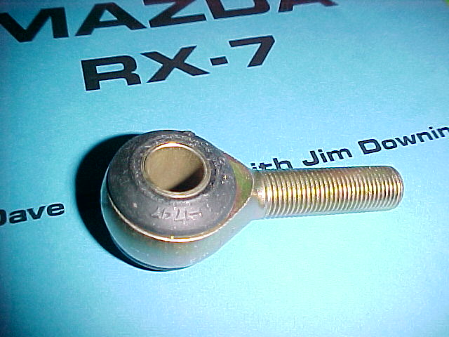
Don't be freaked out by the 1/2 inch bolt going through the rubber ball
joint as that is what they need.
This is not a big enough market to make NC parts.
Paul Lamar
--
The Rotary Engine NewsLetter. Powered by Linux.
ACRE NL web site.
http://www.rotaryeng.net
Youtube key word UTUBPLEASE
Copyright 1998-2009 All world wide rights reserved.