Paul,
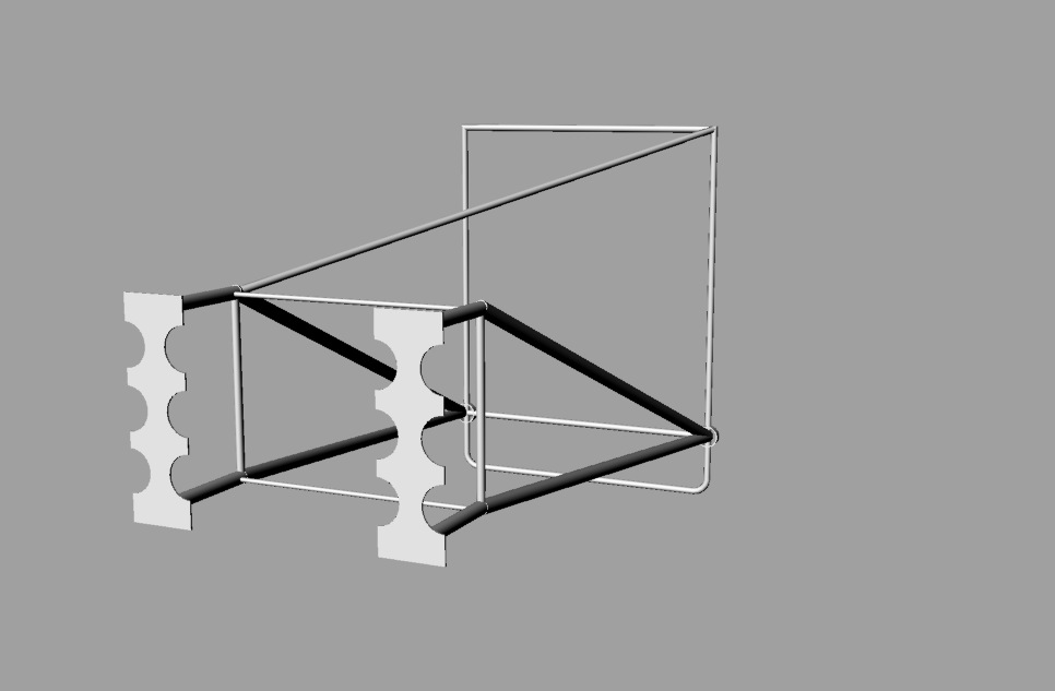
Thanks for the advise with Rhino. I was able to get most of the motor
motor frame modelled to within several millimeter of accuracy. Length,
the important measurement is spot on.
I enter X,Y, and or Z coordinate for most of the work but I can't seem
to get it to work for the final 3/4 (19mm) pipes angling upwards and
outwards from the rear junction to the front face.
I need to draw in the lower cross bracing as well.
Now stumped. I've accurately set points (checking the three views to
tweak and verify their position but when I try to run a regular line
between them, the line goes in a completely wrong direction. On the
first set of angle pipes it worked but not on the opposite side. I
mirrowed them and dragged them into position. Everything you see is
Boolean connected now.
Is there any way to select (highlight) the desired two points and then
command a line to go between them?
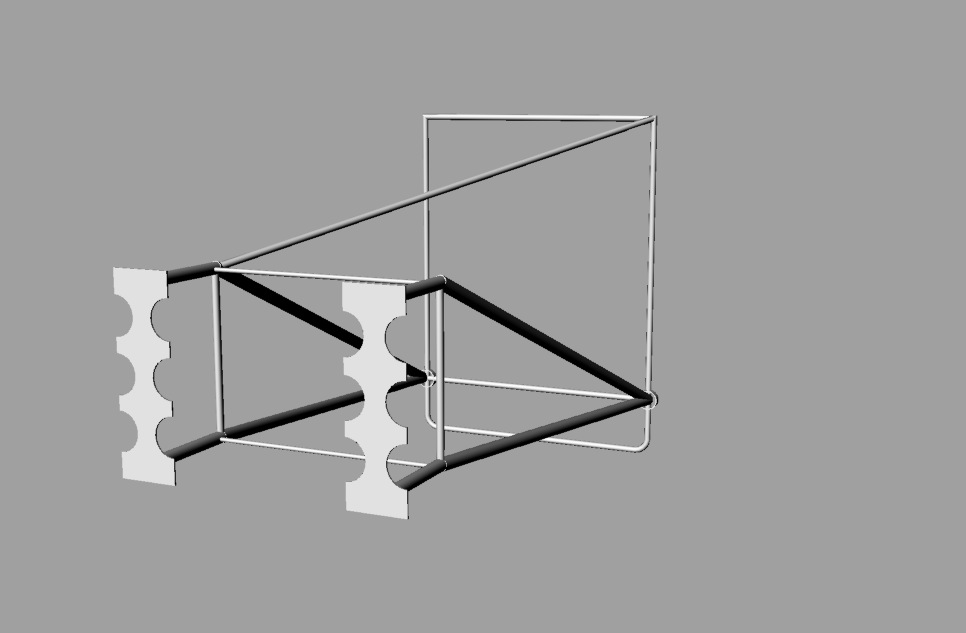
Attached is a JPEG of how far its come.
Oh yea I am using Version 4 for the Mac and being a trial program it is
buggy. No one has reported this bug yet.
Doug in Japan
That is looking pretty good Doug. You need to triangulate those
first couple of bays.
You can choose two points out of plane in the perspective
view and snap a line between them.
Paul Lamar
The Rotary Engine NewsLetter. Powered by Linux.
ACRE NL web site.
http://www.rotaryeng.net
Youtube key word UTUBPLEASE
Copyright 1998-2009 All world wide rights reserved.
--
The Rotary Engine NewsLetter. Powered by Linux.
ACRE NL web site.
http://www.rotaryeng.net
Youtube key word UTUBPLEASE
Copyright 1998-2009 All world wide rights reserved.