Another ignition question. Since my Renesis has four coils and one of the
respondents to my past questions mentioned setting one VRS at 20 and
another
at 27 degrees BTDC, How would it work out to have an on/off switch on the
27
degree VRS with a separate EDIS-4 controler to the trailing plugs and turn
it on after the engine is started, thereby running the engine with the lead
and trailing plugs 7 degrees apart.
Since the color coded plug wires are different to the VRS and EDIS-4, how
do
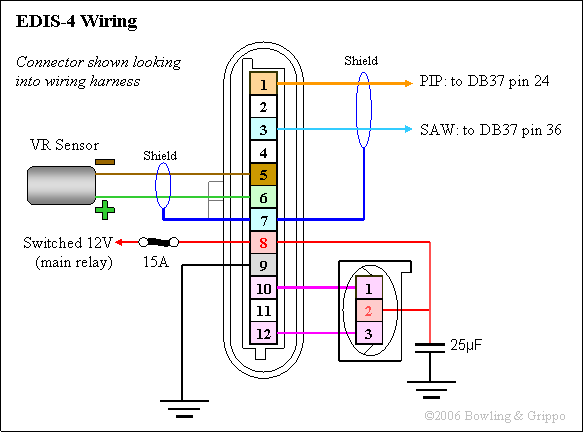
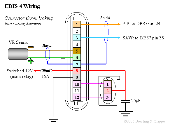
you determine the positive and negative wires out of the VRS ? (The
schematic shows a + and a - )
Karibian
Karibian, The VR + is the green wire and goes to pin 6 on your EDIS
The VR- is the brown wire and goes to pin 5 on your EDIS
The shield wire goes to pin 7 and as usual only one end of a
cable shield can be grounded for it to function
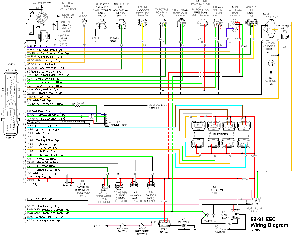
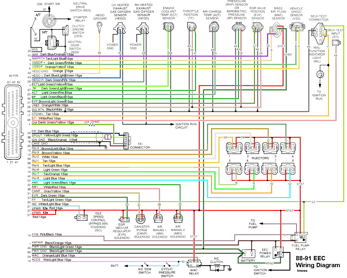
I will attempt to do an attachment on Ford wireing but as usual there
is never a small child around when you need one for these computer
operations.The EEC IV diagram is downloaded from Bob Cooke racing I don't
know where I found the EDIS diagram.
george grimes
--
The Rotary Engine NewsLetter. Powered by Linux.
ACRE NL web site.
http://www.rotaryeng.net
Youtube key word PaulLamar2
Copyright 1998-2009 All world wide rights reserved.