BTW how many people on here can weld steel?
Paul Lamar
I have been known to fuse metal together...
Not certified or anything. I use mostly TIG.
Chris Cosman
Are you willing to mnake mounts for people?
Paul Lamar
In my tons of spare time.... sure.
It would need to be a for profit operation as I'm currently unemployed
and going to school full time; time to finish up that M.E. degree...
Do you mean, make them from scratch? Weld together a pre-fab tube kit?
What exactly?
Chris
Yes for profit.
Make them from scratch. I'll mass produce and supply firewall and
rubber cup holders.
Paul Lamar
Sounds doable. Count me in.
Are these the motor mounts that you've designed in Rhino?
What was Jerry Hey charging?
Chris Cosman
Yes on the Rhino designs. I don't really know what Jerry was charging.
Paul Lamar
---------------------------------------------------------------------
Chris Cosman, I used to build custom Harley Davidson show bikes for 7 years
as a hobby. My frame/chassis jig had a 68 shovelhead engine mounted off the
surface plate to fit everything clear of, and a slotted plate for rear axle
and stearing head position and angle. You can work much faster when you are
sure everything is OK. I had a spare chrysler engine to set up some
prostock
drag race chassis also a real good deal. Surely someone can donate you some
run out side housings, rotor housings and an accessory cover. I got some
junk irons from Bruce Terrentine at the WWW airport just south of Raleigh
NC a few years ago, or possibly someone on the newsletter has an RX7
suitable for a jig.
I would mount it off the bolt holes on the sides that
mounted it in the car, down to a plate with the center of the E-shaft as a
punch mark. A jack bolt at each corner would be used to set down or side
thrust angles by tilting the plate. The mounting holes attached to the
engine would be soltted 2" for different firewall distances. and the
uprights would be two overlapping 3X3 angle irons with holes drilled on 1"
centers also for adjustment.
The stand in engine could be just end housings separated by threaded
rods to go from 2 rotor to three rotor but an engine core would permit the
muffler etc to be in place to build around. This arrangement would also
facilitate some optional brackets such as the side mount radiator mounts
In addition to the plywood firewall that the engine is sitting on, A
second plywood of the cowl cross section could be bolted to the front of
Jeff's mounting plate to make sure no tubing falls outside the cowling. The
builder could supply a cardboard template fit to his cowl.
Experiance has shown tha cutting the longest pieces first and
fitting each tube as you go saves material. Any tube with more than 1/16"
gap can be recycled to a shorter part. "Not tellin ya yer business" as the
say around here, but when u is old as dirt bin der dun dat.
george grimes
---------------------------------------------------------------
We have been there and done that George on your motor mount scheme
and it does not work well in an aircraft. Probably tens of
thousands of messages have been written on this subject over
a 11 year period.
First: every Mazda rotary engine generation motor mount is
different with the mount starting on the 12A front cover and moving
backwards in generation after generation. It limits what you
can do with the oil pan as the center mount needs a depression
in the oil pan. The current oil pan on the RX8 is inadequate
for air craft use. The third gen engines have the mount on
the back (car) housing. This relieves the block of the torsional
loads and puts the mount near the CG of engine gear box combination.
In almost every case it makes the exhaust manifold or turbo
charger a nightmare to fit in and remove in service. Not to mention
the high heat the rubber bushings are subjected to. That is why we
have moved the MM tubes out and away from the engine with the motor plate.
The current motor plate mount works with all generations
as the engine, gear box, prop and starter combo moves the CG near the
rear (car) housing. The motor plate does double duty and saves
a lot of weight. It also puts the 500 to 600 ft. pound (avg) prop
torque directly into the rubber bushings where it must go sooner
or later.
I want to standardize as much as possible to keep the cost within
reason. It has taken us 11 years to evolve this mount and I am not
about to go backwards. Probably a 100 mounts have already been built
with many flying. Mostly with the Schertz beam which is a variation
but the same idea.
Reread :
http://www.rotaryeng.net/mm-instruct.html
Paul Lamar
Paul, I am definitely NOT talking about changing the attach points to
something different than Jeff's front plate and a rear stabalizer mount.
The reference to the stock mounting points is meant to be a place to
position a junk core engine in the jig from a point that is never used in
aircraft mounting. Only some attachment to whatever core engine you find to
attach Jeff's plate to, and the rear mounting bracket to, with the option of
mounting the muffler to it. The point is to have a 3D object to fit the
tubing around so that the builder doesn't discover a tube rubbing the oil
pan or a diagonal brace in front of an exhaust port.
I realize that most of the mounting will be basically a bed mount
below the exhaust ports, however the tangential muffler looks to be in that
area and the firewall upper mounts are above the center of the engine.
Having the largest items (engine, water radiator, muffler) physically
present should optimize space utilization of the cowl volume resulting in a
more neatly organized finished appearance.
I found in doing motorcycle frames that just having some
engine weight attached to the structure helped when tapping a tube into
place. The bike frames require an asthetically pleasing combination of
mechanical components and the arcs and straight lines of the structure must
flow with the outlines of the engine. And in a race car there is an order to
things. First the engine crankshaft position as a datum, then
steering, exhaust headers, and cooling in that order. Engine installations
are also an assembly of several major components which interrelate to each
other.
The prop flange referenced off the firewall determines the location
of a lot of the bulky components, and the most negotiable component is the
mounting tubimg. A 3D cad model is a great start and if the model of the
engine is well detailed with the alternator and waterpump outlets among
other things represented then the real world mount will fit .
george grimes
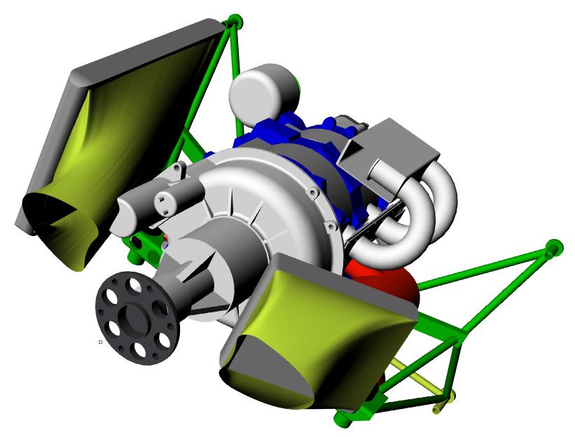
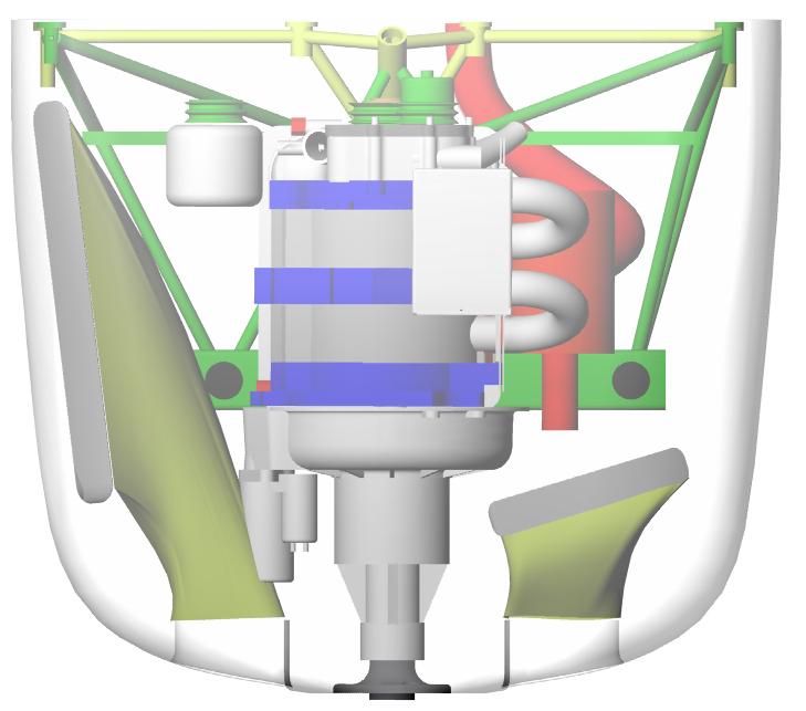
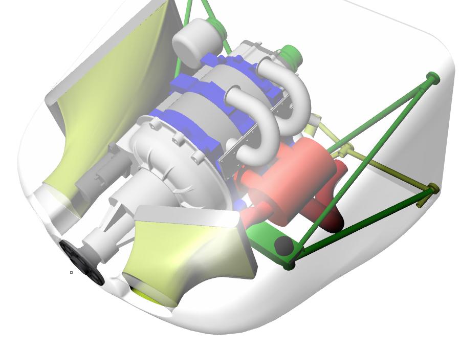
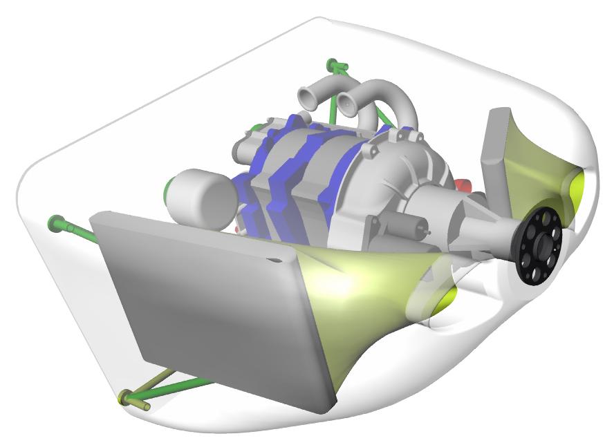
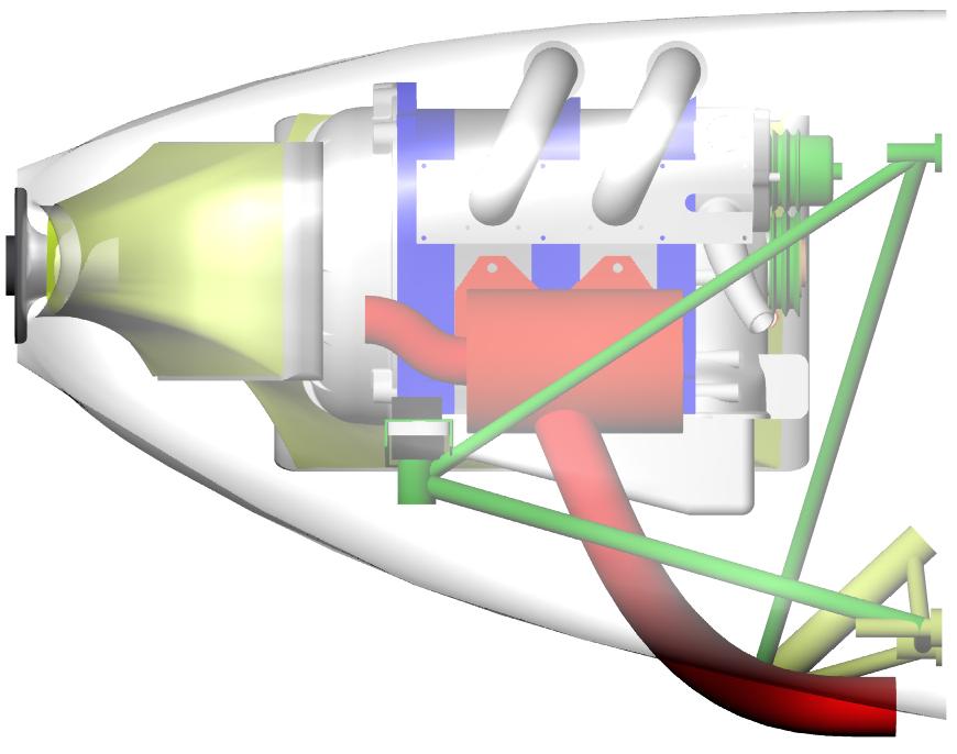
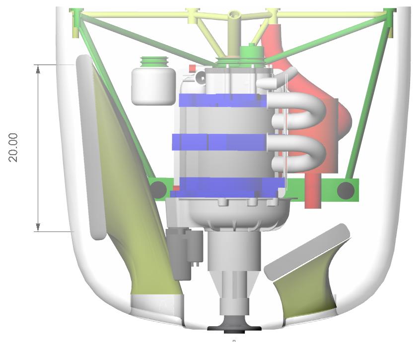
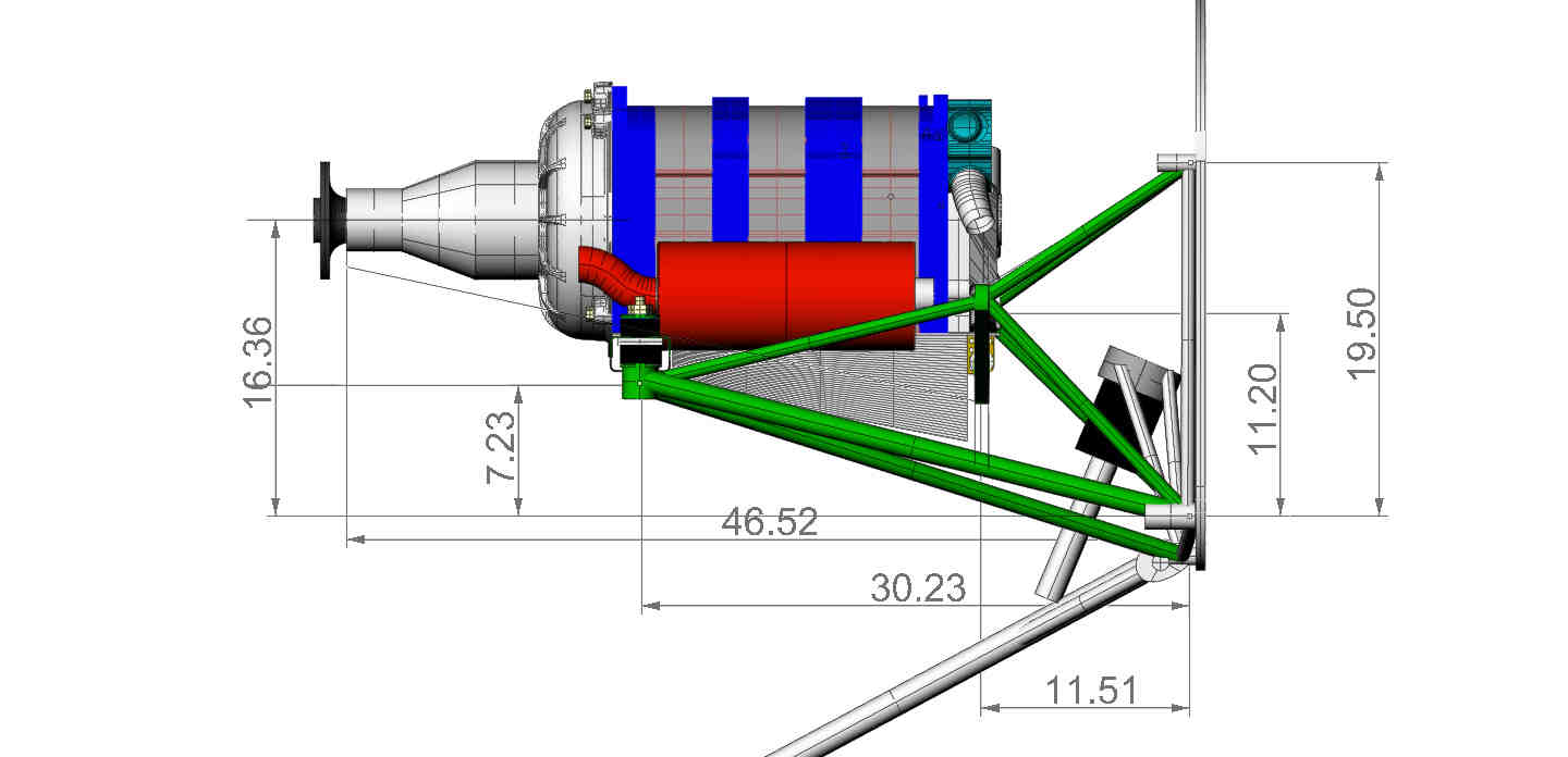
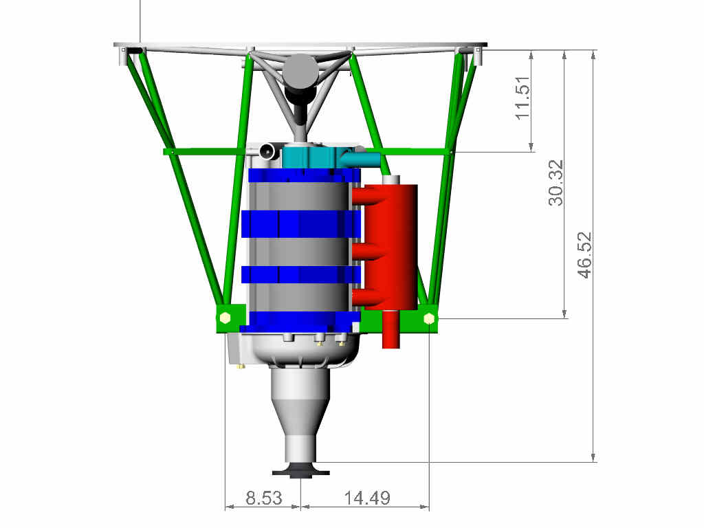
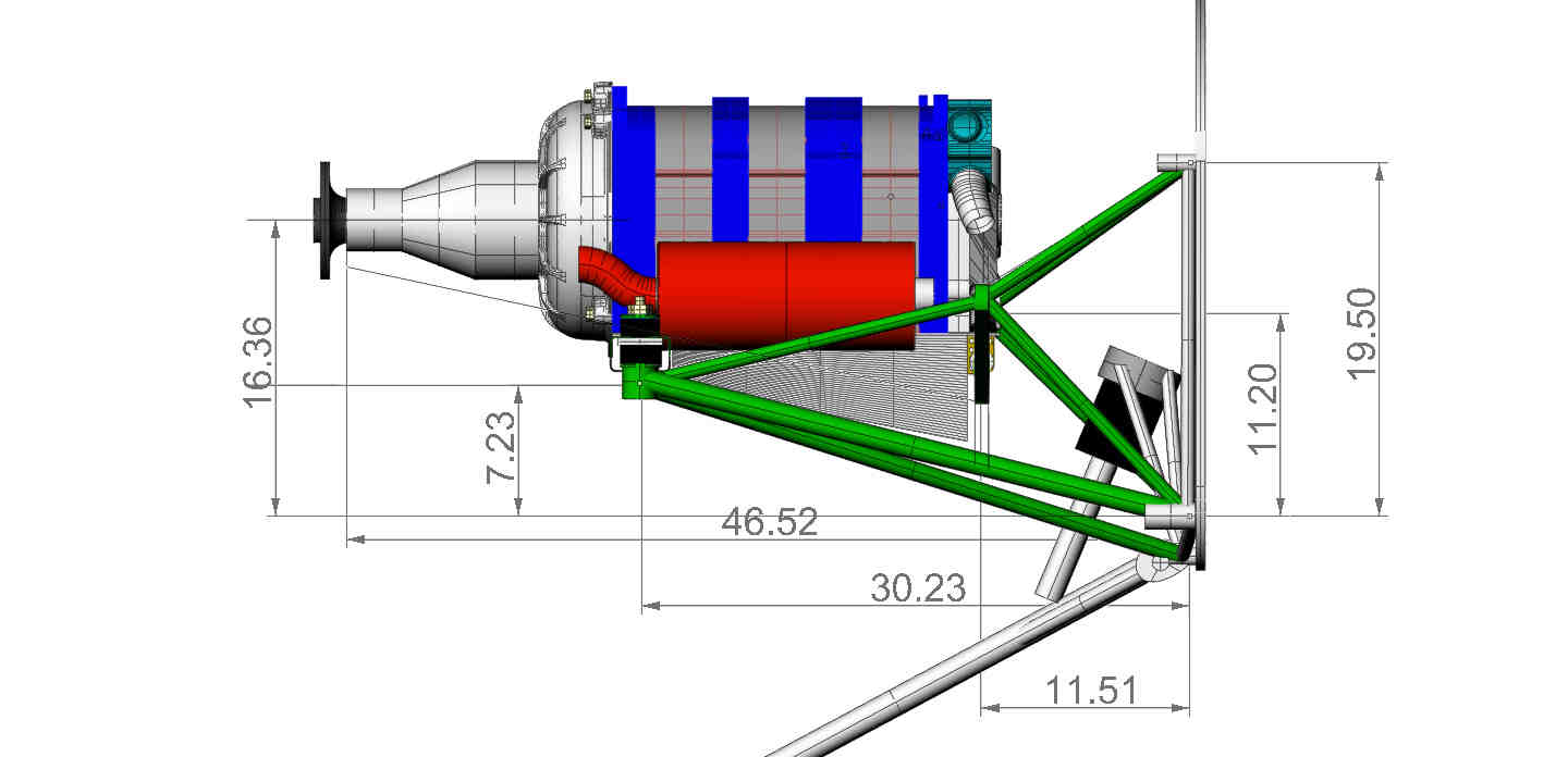
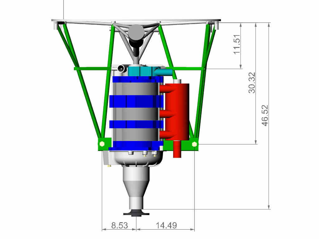
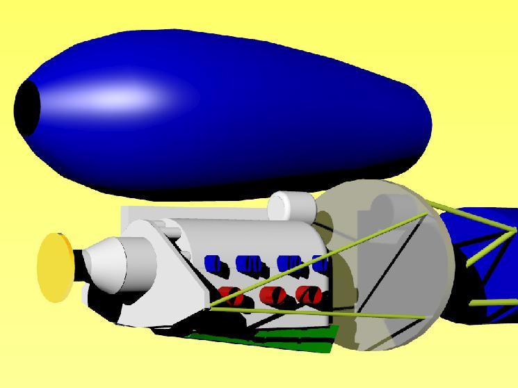
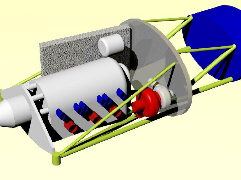
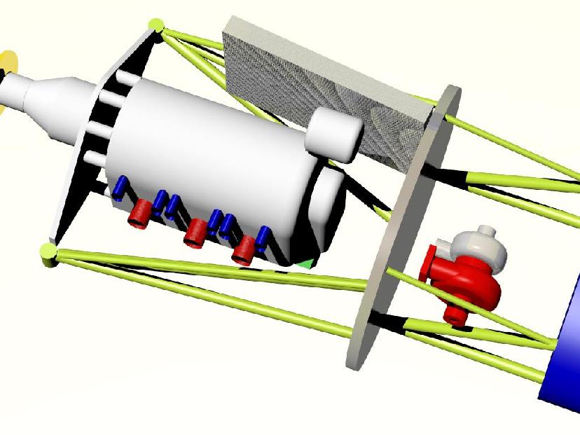
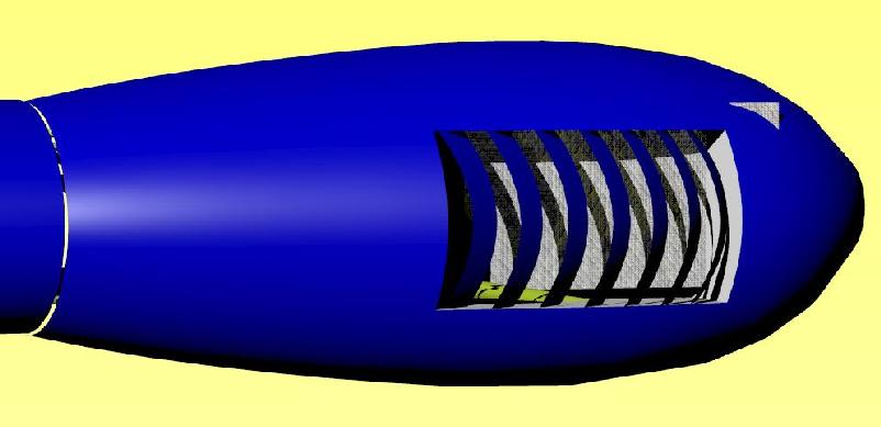
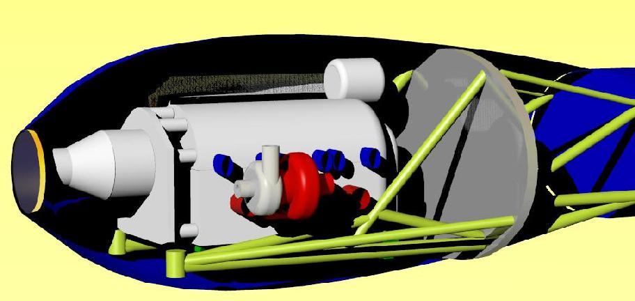
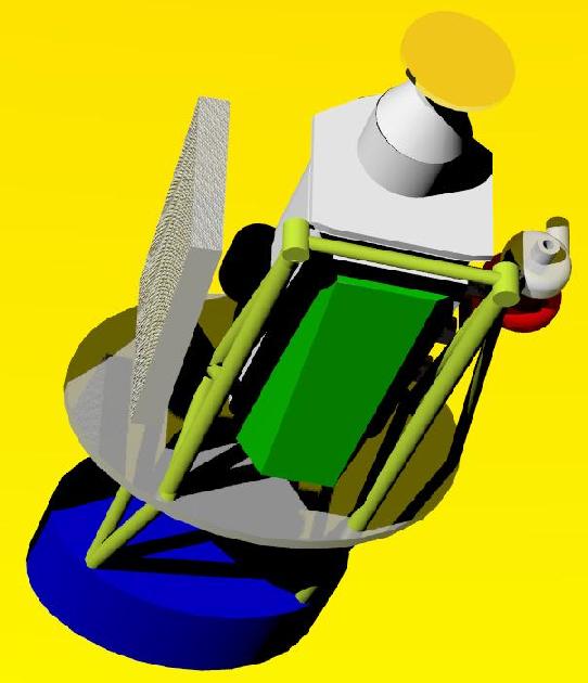
Some 3D renderings would help you make your talking points.
I don't see the need for the engine in the motor mount
fabricating process.
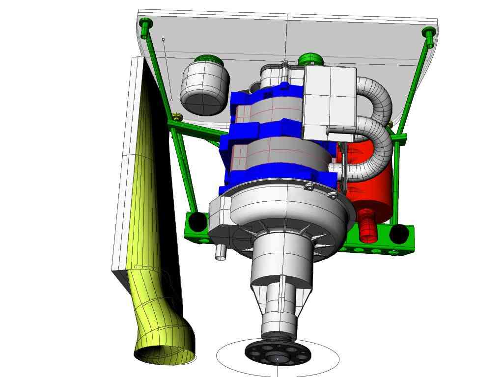
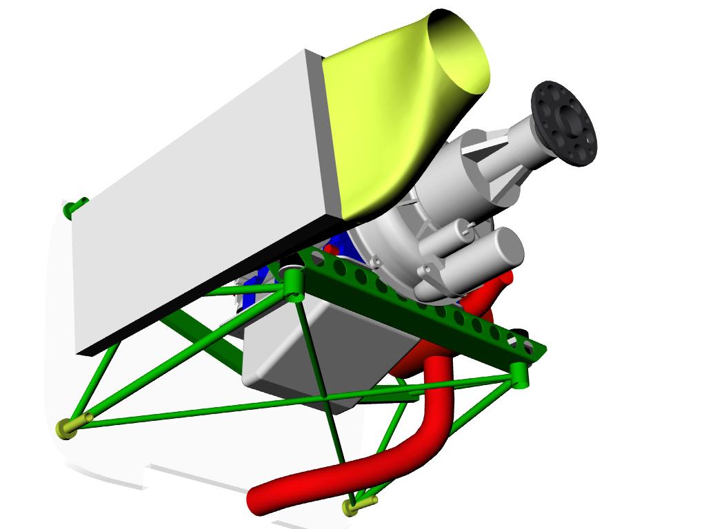
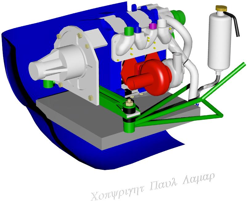
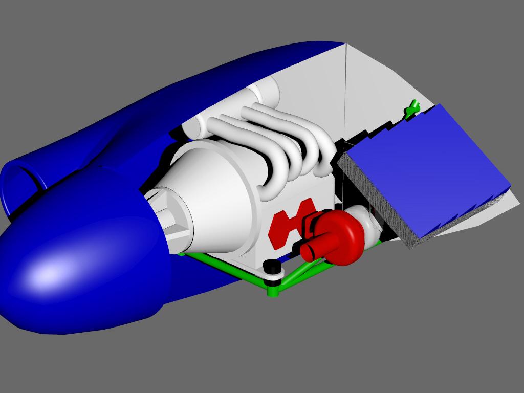
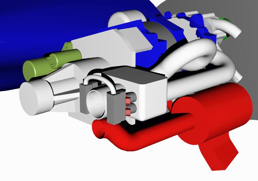
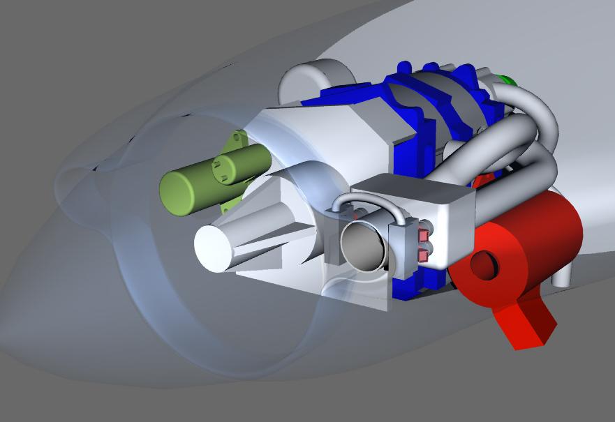
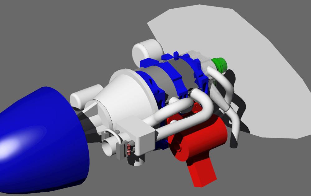
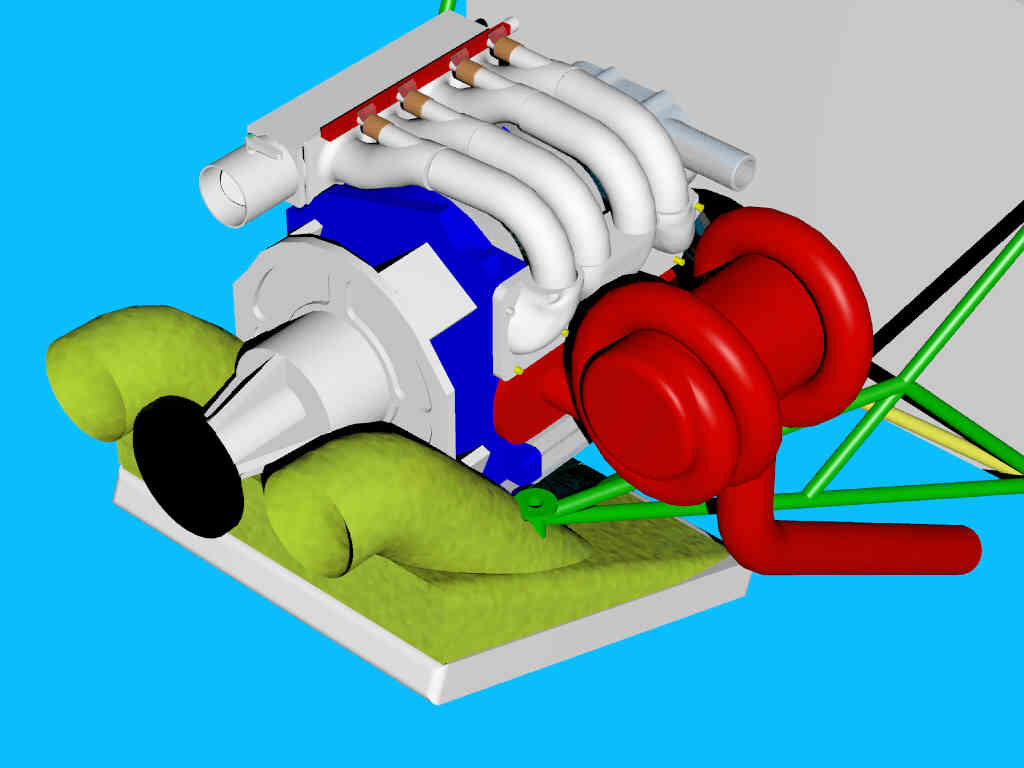
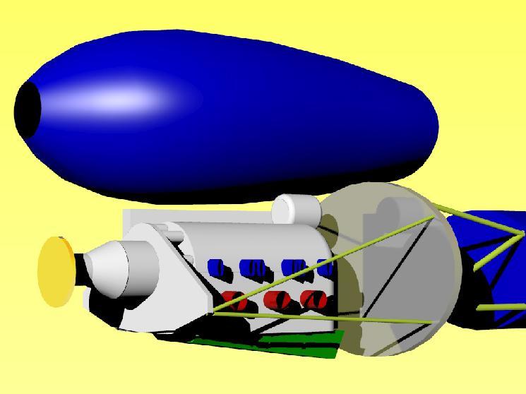
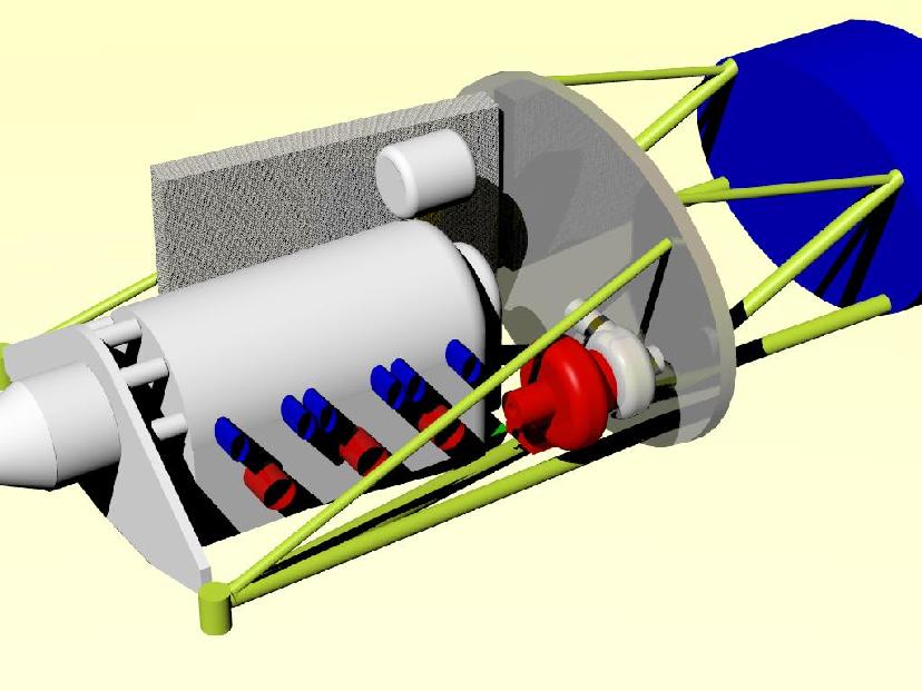
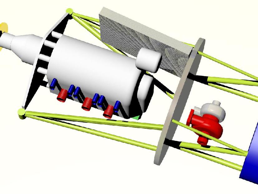
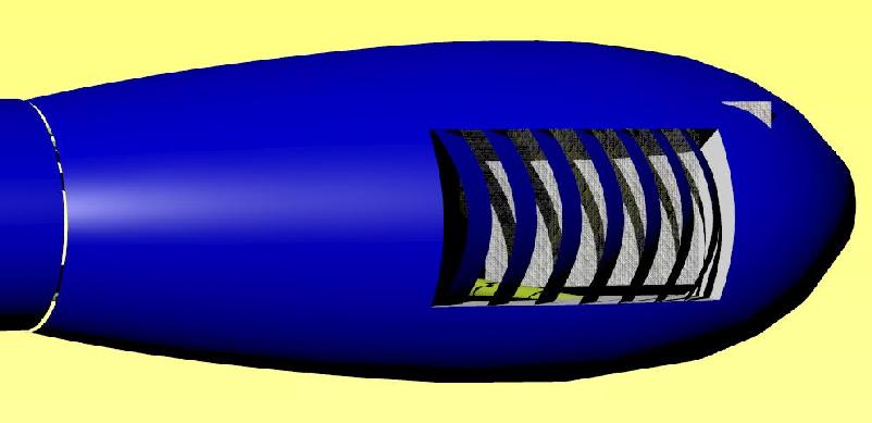
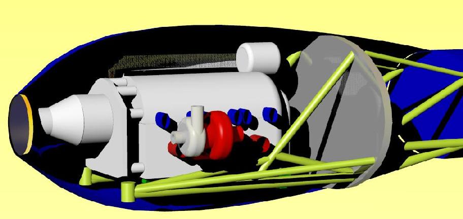
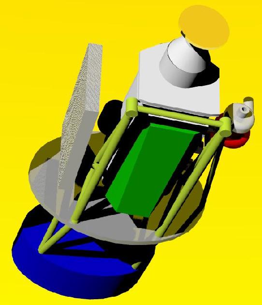
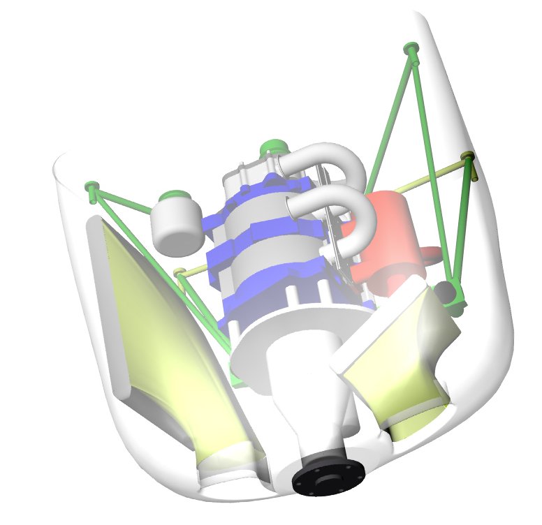
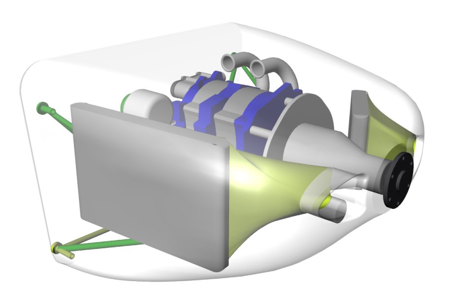
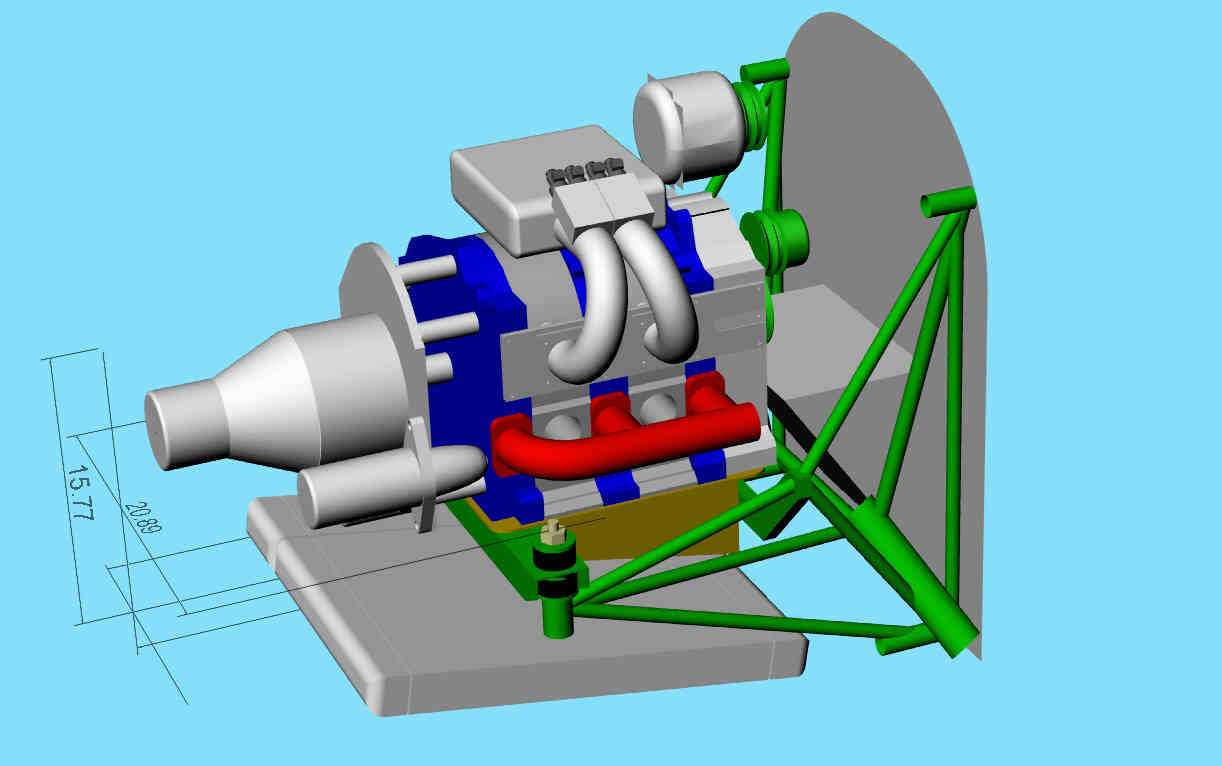
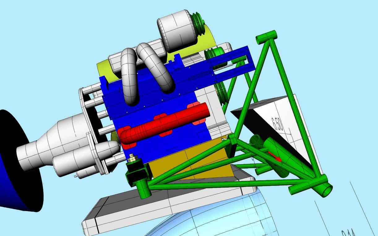
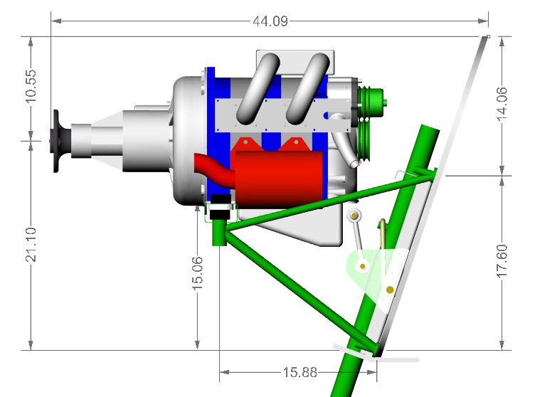
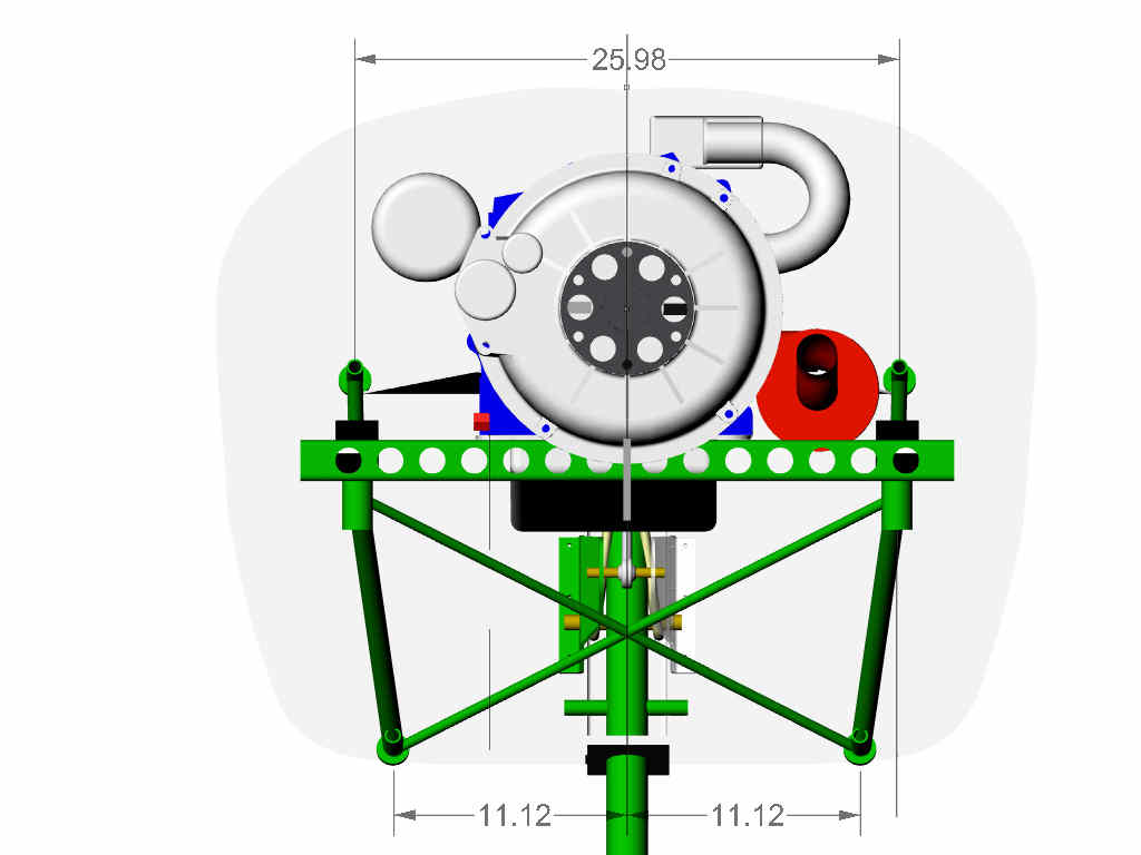
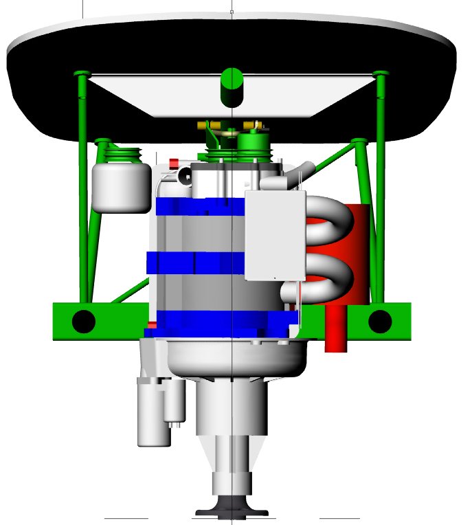
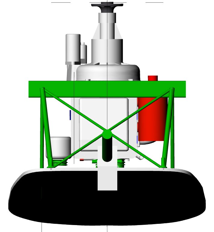
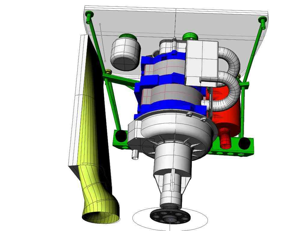
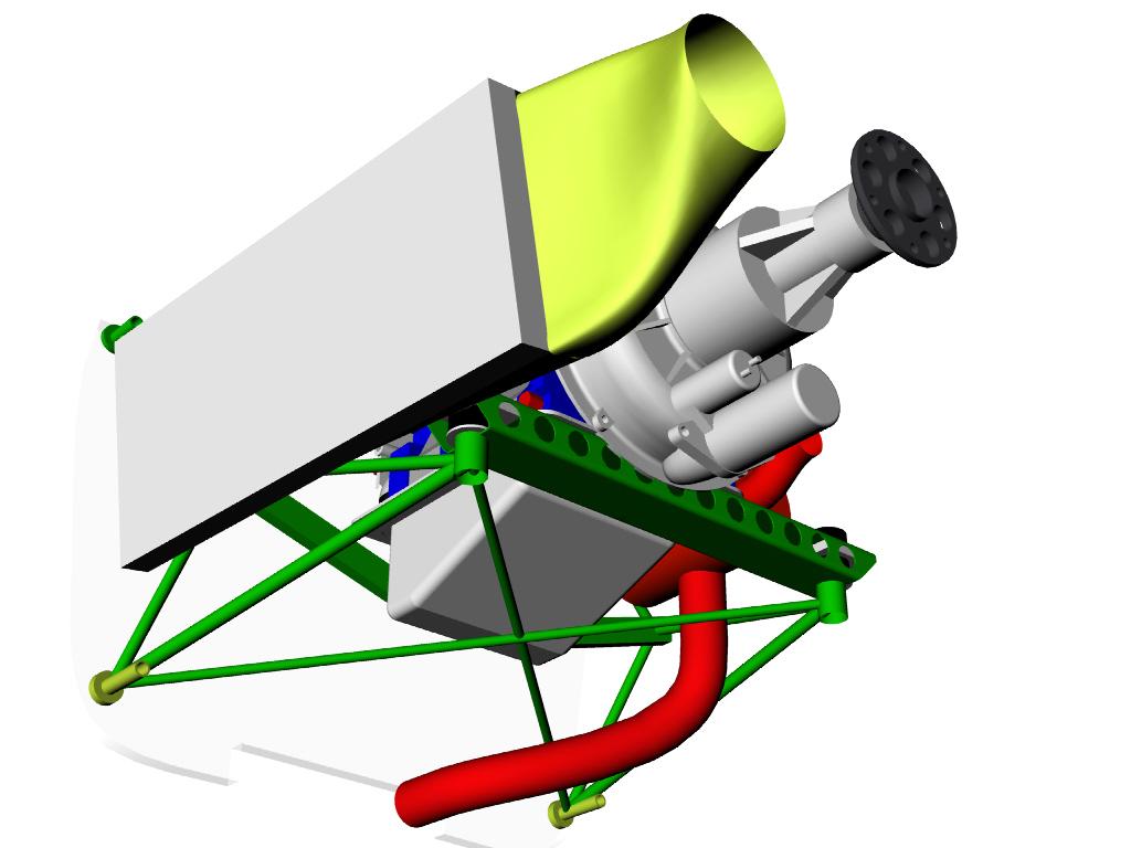
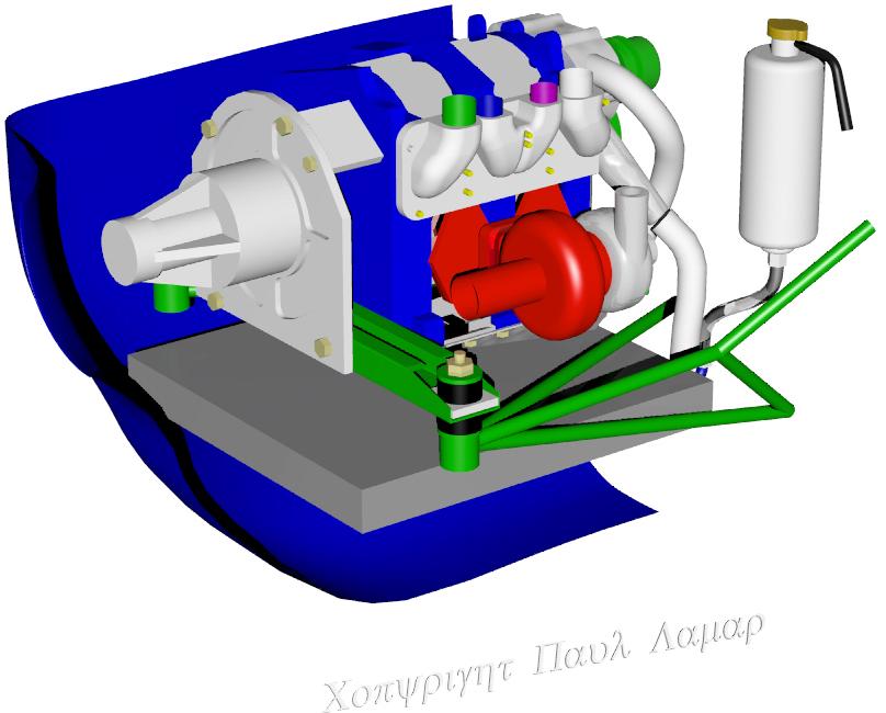
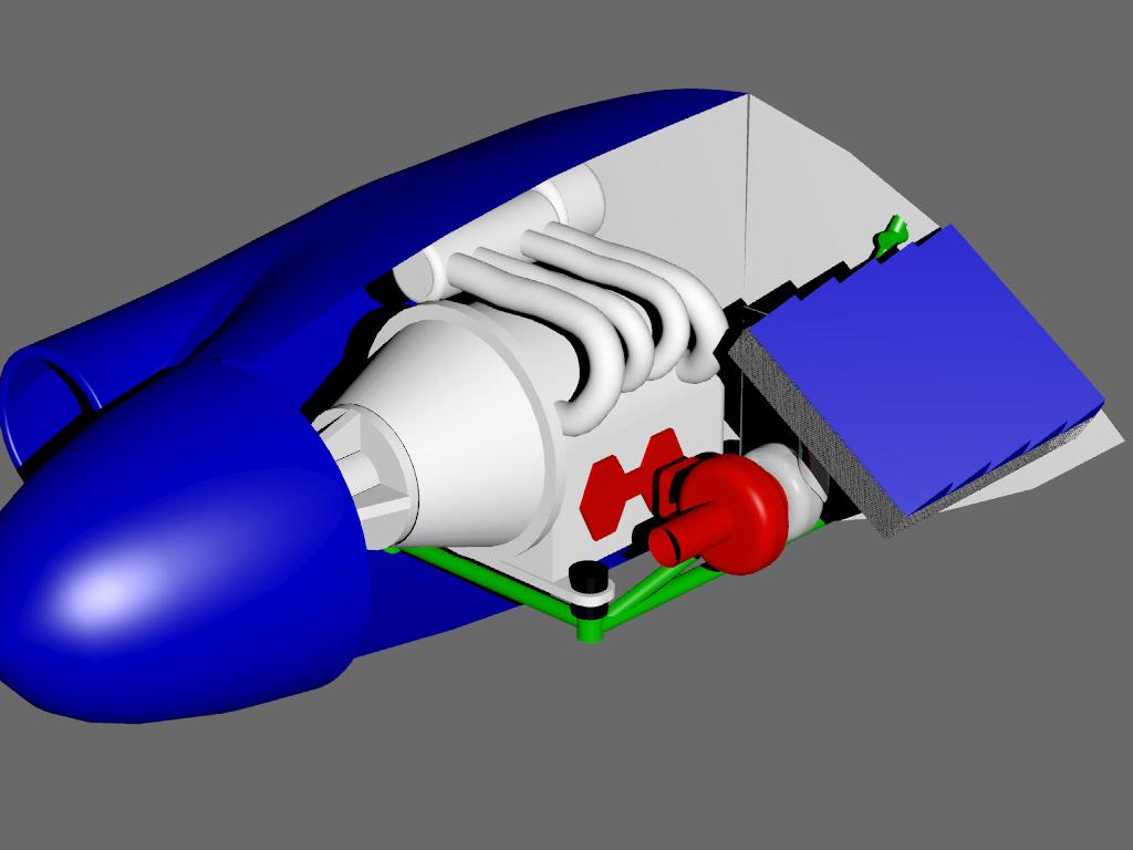
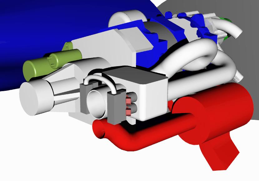
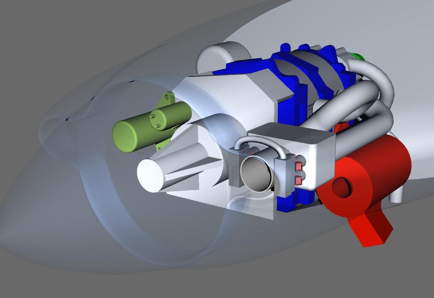
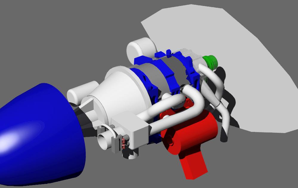
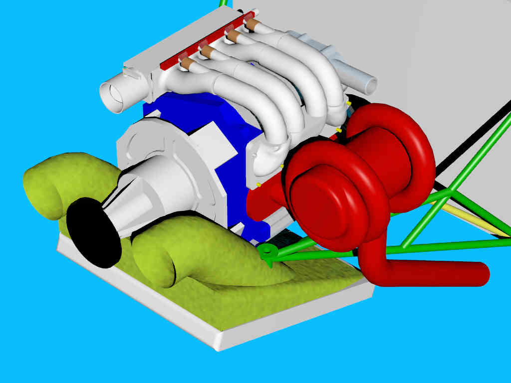
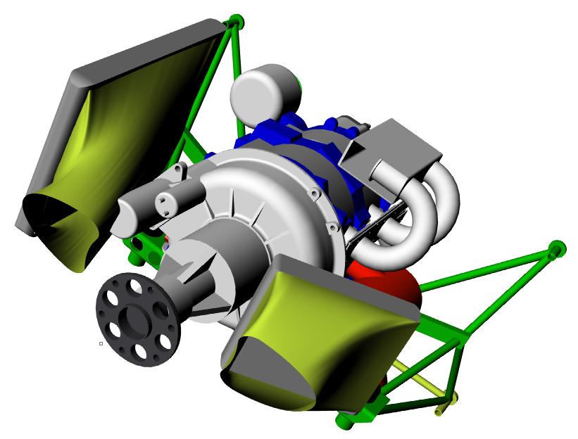
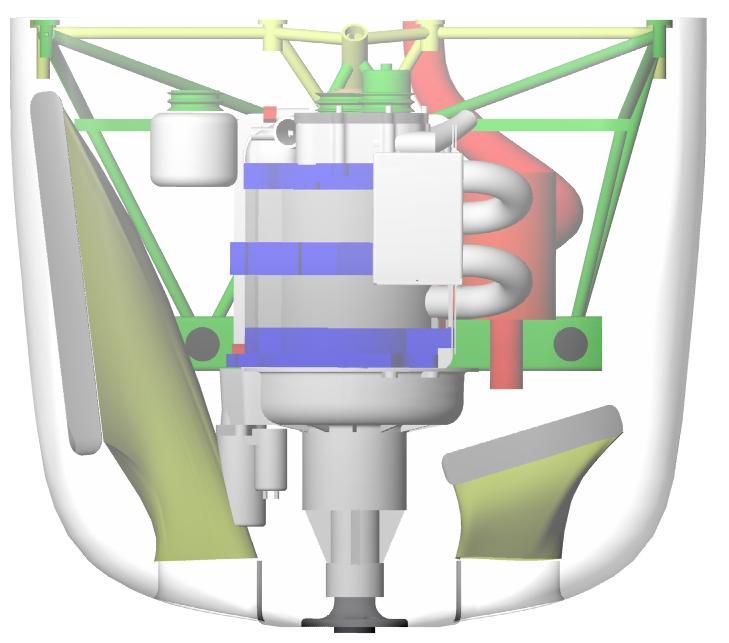
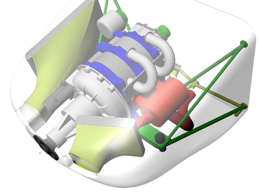
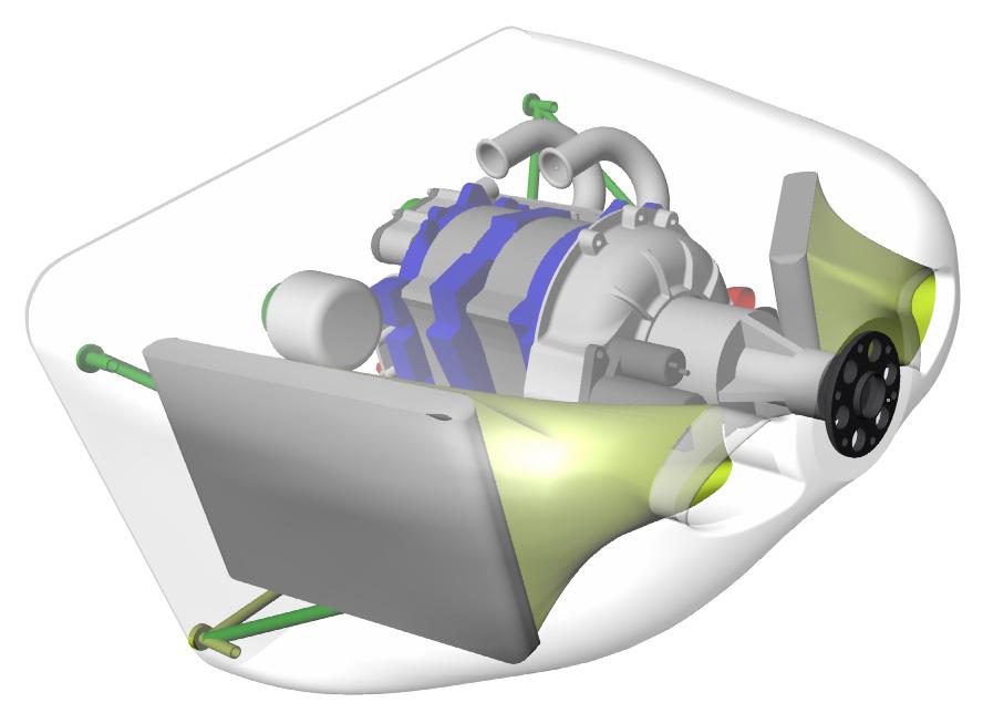
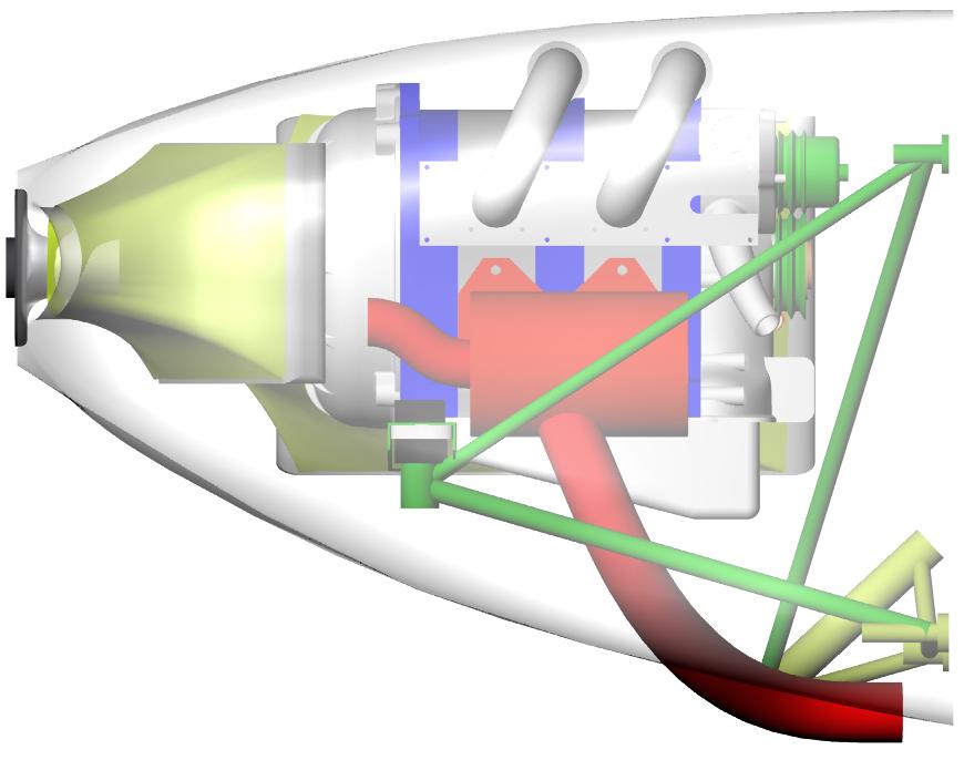
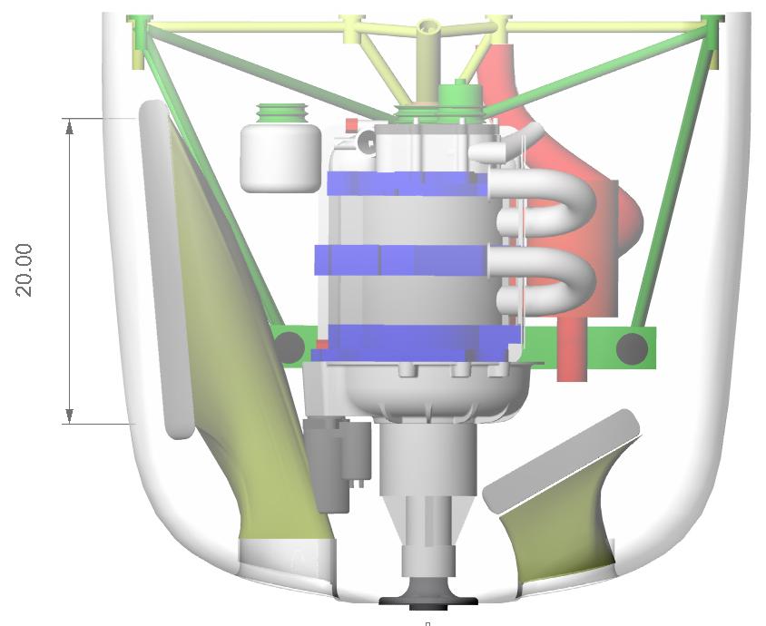
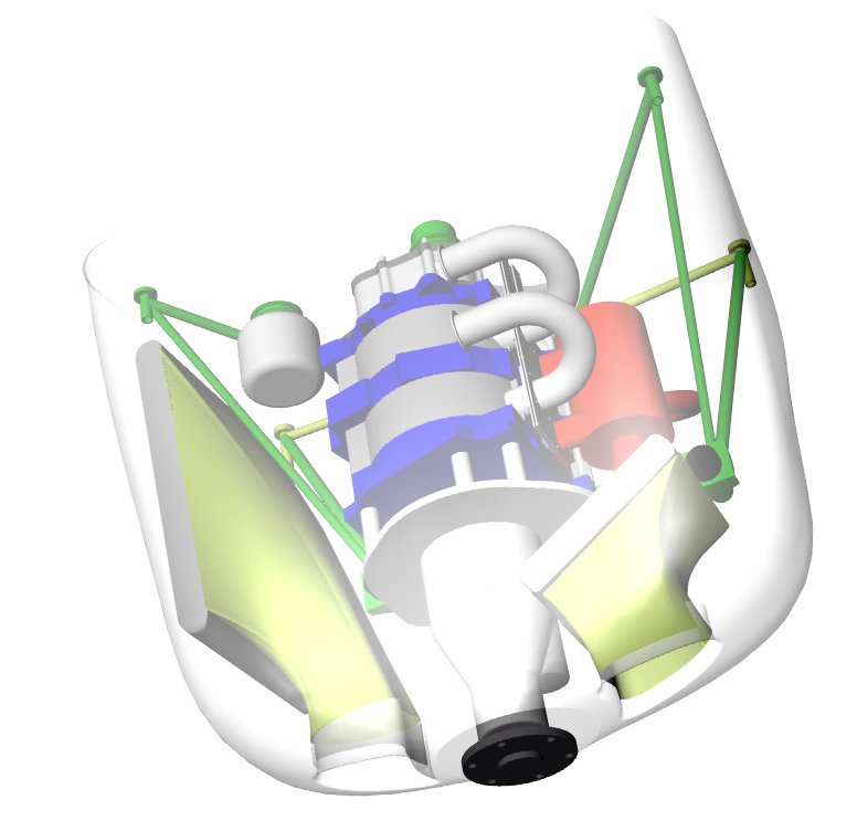
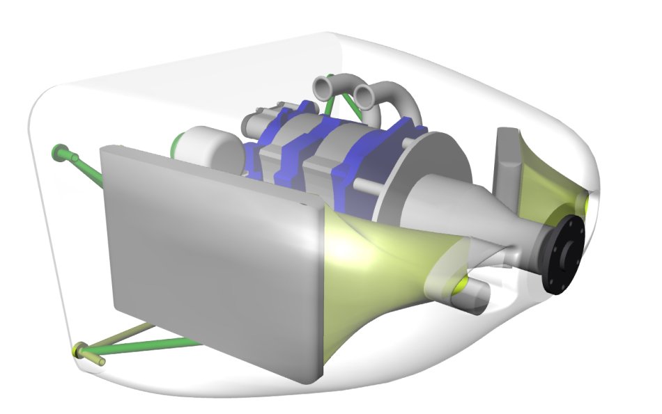
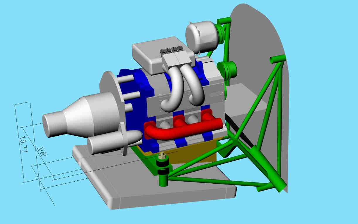
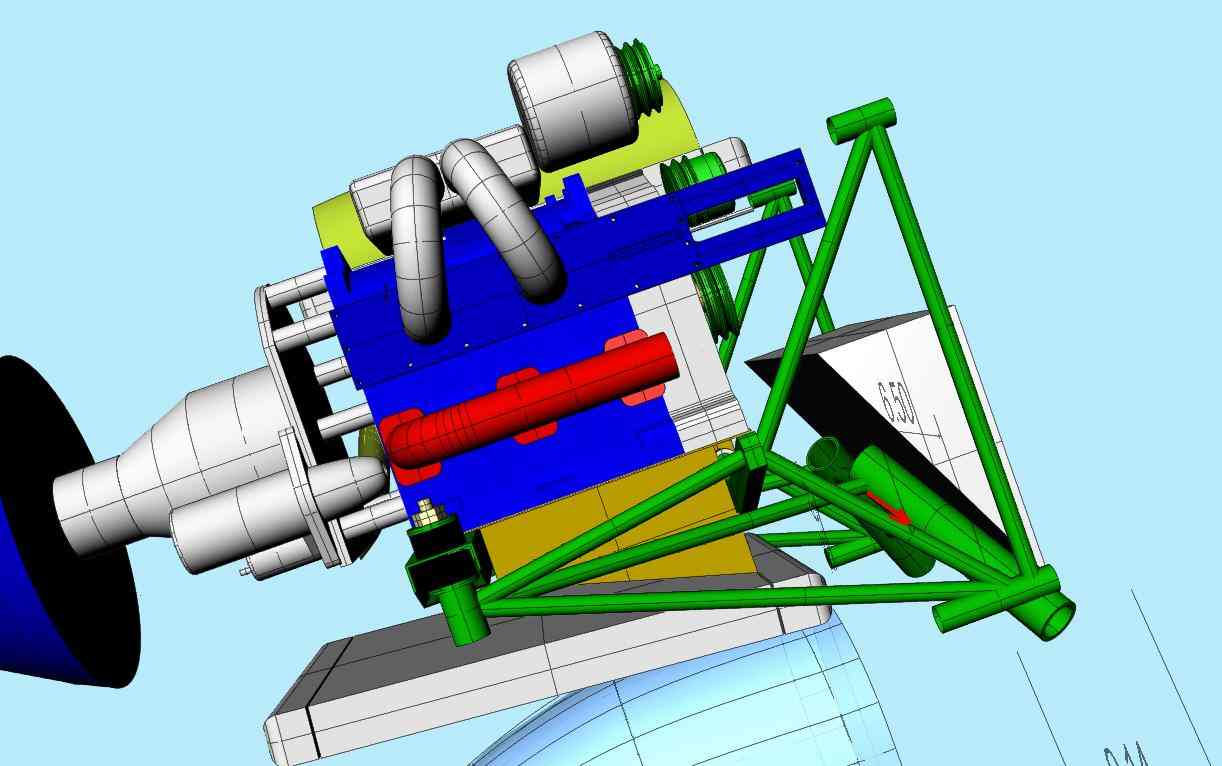
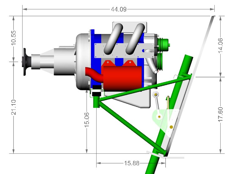
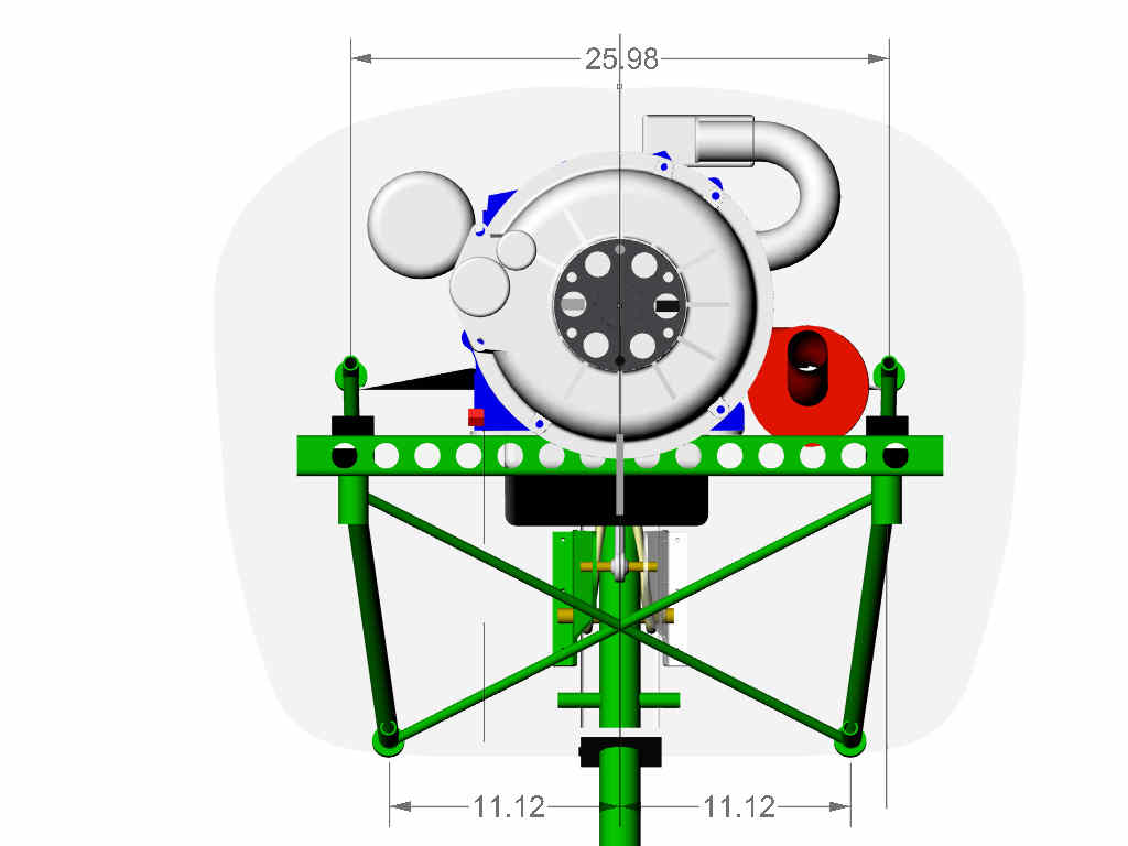
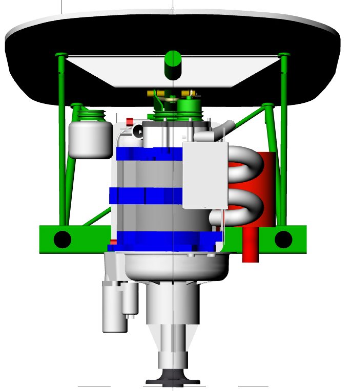
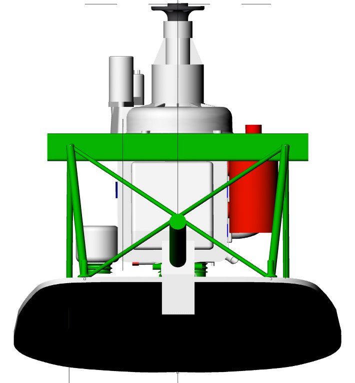
When I design a mount all important objects within the cowl are placed
in the 3D renderings. Here are just a few of the hundred or more
that have been done so far.
Paul Lamar
--
The Rotary Engine NewsLetter. Powered by Linux.
ACRE NL web site.
http://www.rotaryeng.net
Youtube key word PaulLamar2
Copyright 1998-2009 All world wide rights reserved.