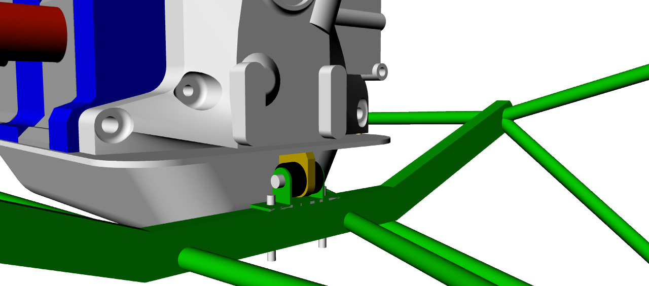
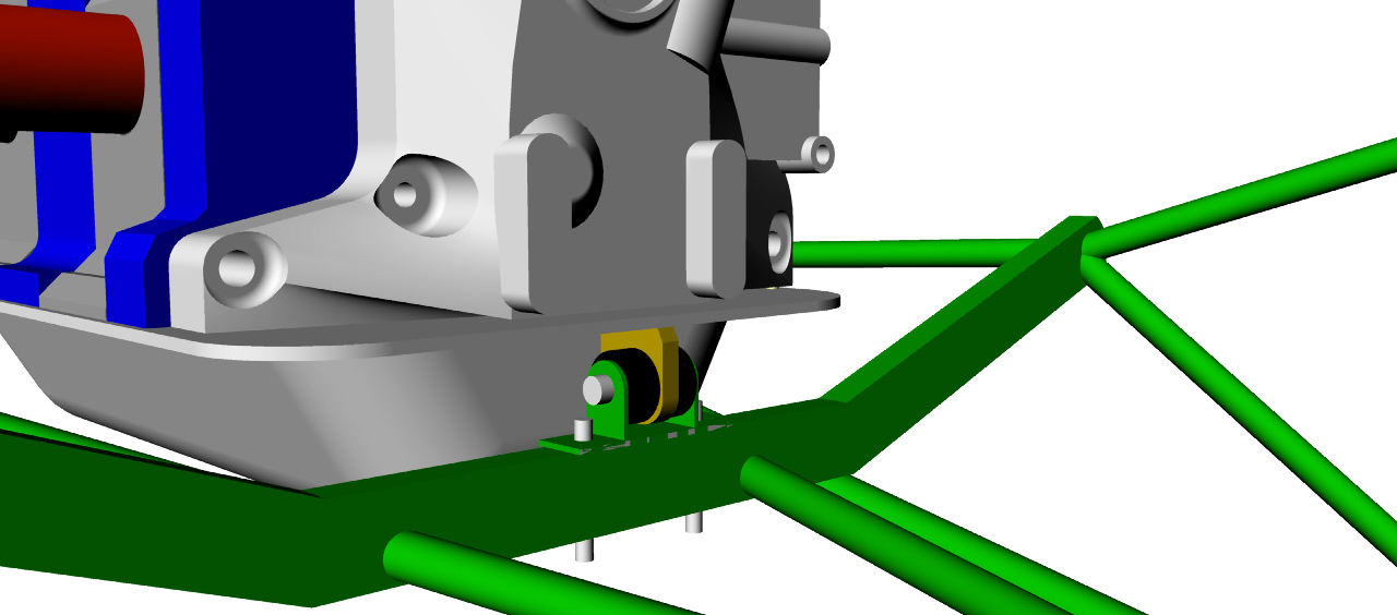
Yes here is a 3 rotor version using the schertz beam.
I'll redo if for Jeff's motor plate shortly.
Paul Lamar
Thanks Paul !
Don Mitchell
Here is what it looks like.
-----------------------------------------------
Delete all of those old jpgs. Reset!
I have found a way to simplify the mount and remove
a few tubes of those tubes.
Here are the new 3D's.
Replace them with these.
-------------------------------------------
Here is what the cowling could look like.
There is tons of room in there for a large
rad.
Paul Lamar
Yeah, that looks great!!! Can you tell how much room there will be
over the top of the engine? That always been my concern......having
room to cross over with the intake manifold.
Don Mitchell
Hard to say without a stock RV10 cowl dwg.
It is going to be tight as the thrust lines is only 10 inches
down from the top of the cowl. You will need a low
profile water pump.
If you have the stock cowl set it up in the corner of a room
and make some measurements of the side view on the cowl
center line and send them to me. Same for the width
measurements. Try to do it every 10 inches along the length
and I can reproduce the cowl dwg in 3D.
Another way is use a long lens
on a digital camera perpendicular to the top and perpendicular
to the side.
Here is a 3D guess side view.
Paul Lamar
Paul,
Those drawings are great ! I wish I could figure out how to do
that!!! Can you send detailed drawings of the mount with dimensions
of the individual tubes ? How must clearance is safe between the
exhaust header and the mount tube?
Don
I am not sure I have it right. Do you have a RV10 cowl?
Paul Lamar
No, unfortunately I didn't buy the entire kit yet. Will have to
put the
mount on hold until Summer when the cowl comes. I've just been
enjoying
taking a break to work on the engine over the Winter, and was hoping
to test
run using the actual motor mount on a test stand.
Don
Well Jerry Hey did a couple before as I recall. One RV10 for Bobby
Hughes
down in Austin. If you have a couple of days you might go down
there and talk to those guys as there are at least three 3 rotor
aircraft in the works in the Austin area.
Mark Steitle has been flying his Lancair ES
for quite some time and I think Bobby Hughes has flown his RV10.
It is rather unusually as it is a supercharged 2 rotor instead
of a 3 rotor as one might expect to find in an RV10. If Bobby says
the cowl fit OK I have the critical dimensions for that installation.
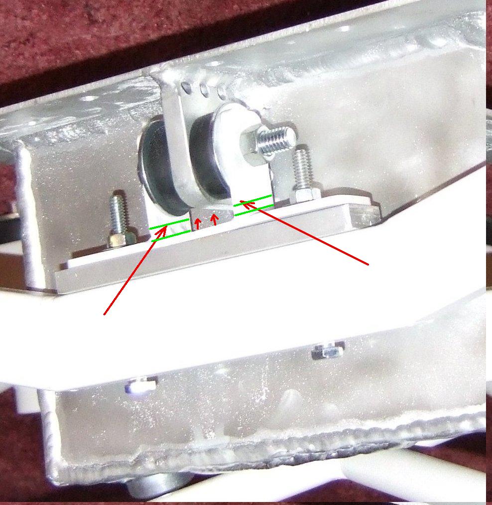
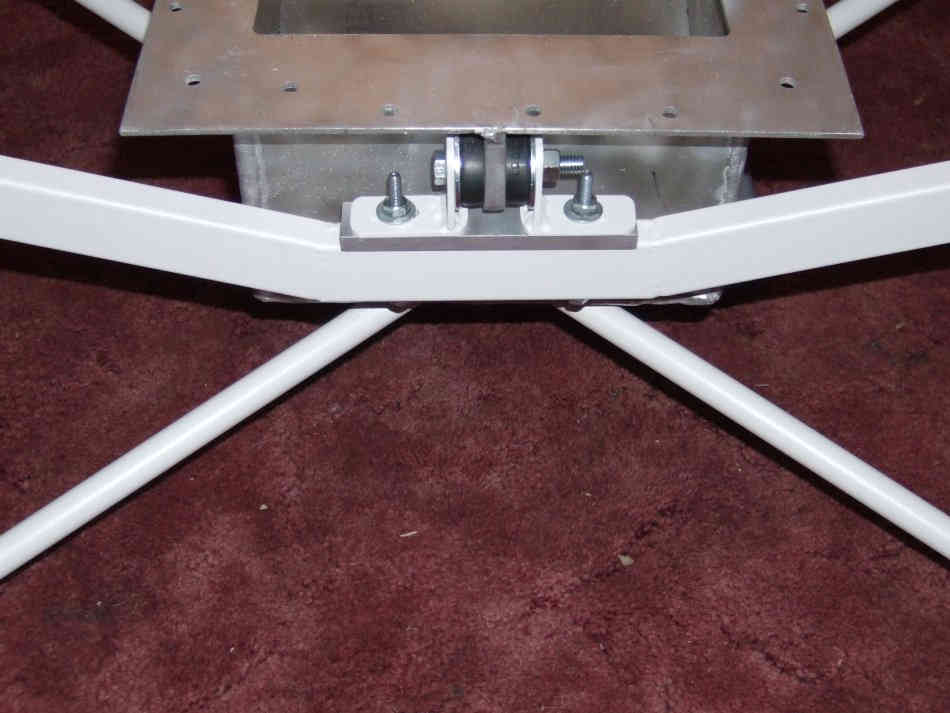
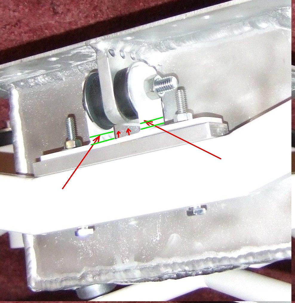
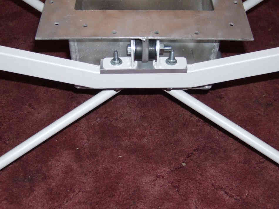
Bobby had some problems with the mount Jerry welded.
It appears the cups were welded on at the wrong angle pointing up
the need for an accurate motor mount welding jig.
Exhaust heat may have caused a problem as well judging from
the attached pictures. The stock RX8 exhaust manifold
was used and it wrapped around the Schertz beam transferring a
lot of heat into the steel Schertz beam and rubber MM bushing.
Supercharged engines generate an ungodly amount of exhaust heat.
A 250 HP supercharged engine is making 300 HP internally due
to the HP consumed by the supercharger. A turbo on the other
hand is using mostly waste HP from the exhaust.
Jeff's motor plate is further away and it can be easily shielded
from the stock RX8 exhaust manifold. Not a factor for you as your
engine is
a 3 rotor and your exhaust manifold of necessity will be entirely
different and much further away due to the p-port exhaust.
What I need to find out is; if at least the RV10 cowl fit Bobby's
airplane.
Paul Lamar
That would be really helpful if we could find out from Bobby about his
mount!!! I was also wondering....how far through the cowl do we need
the prop flange to stick out for the spinner to cowl clearance to be
correct? Also, on the part of the mount that connects the beam to the
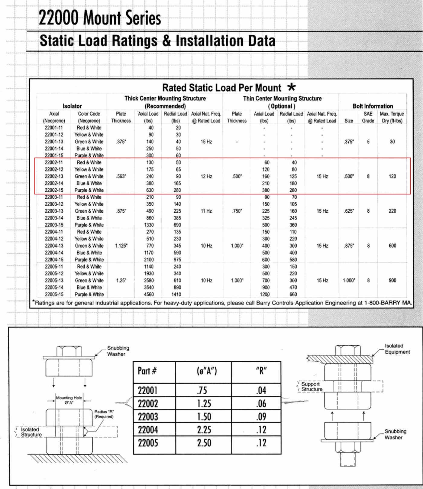
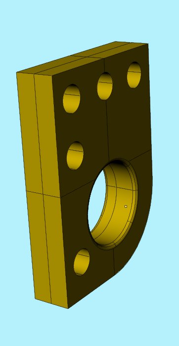
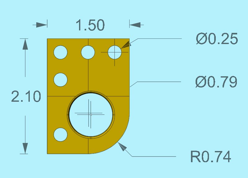
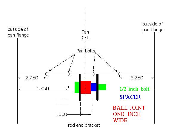
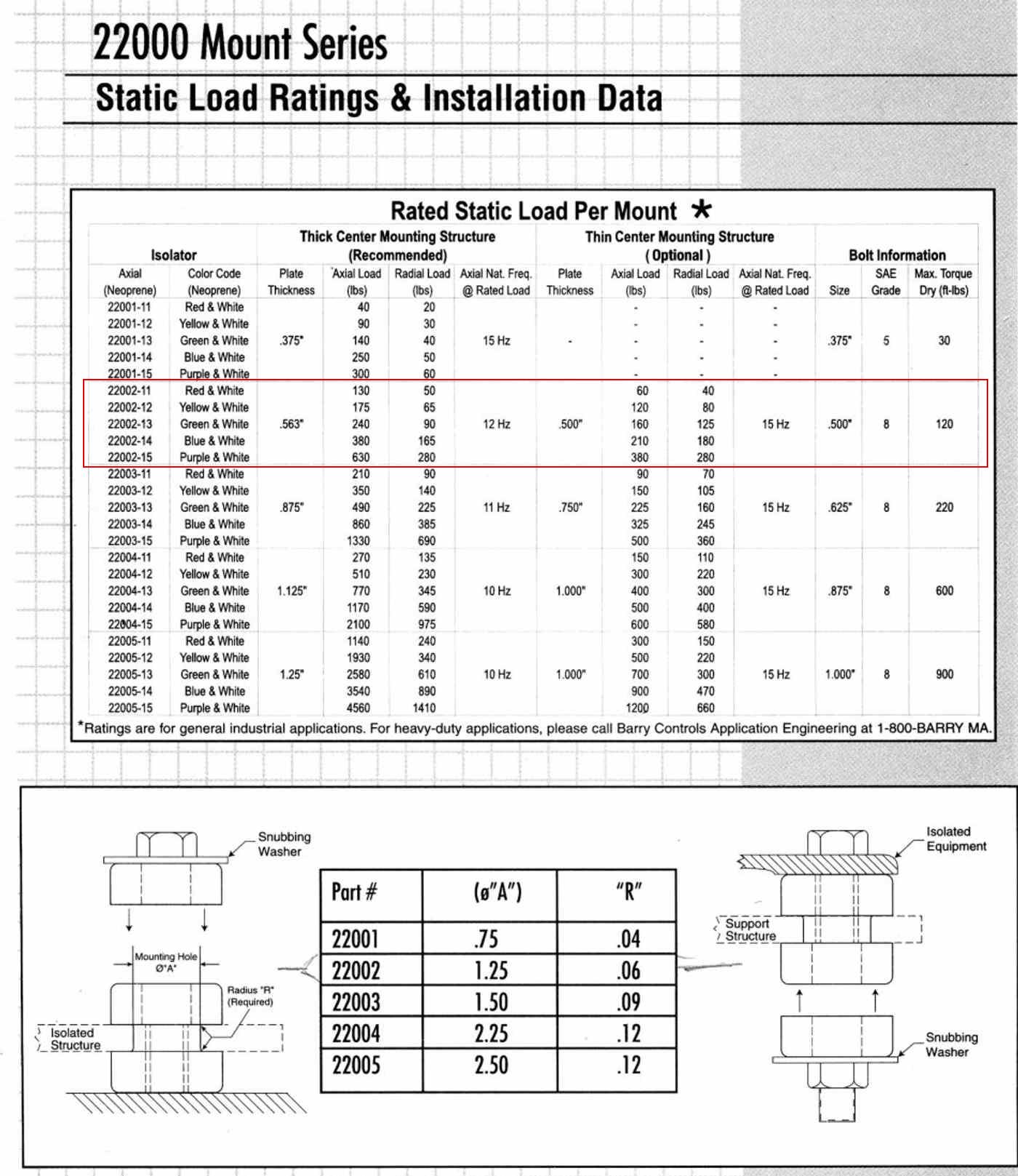
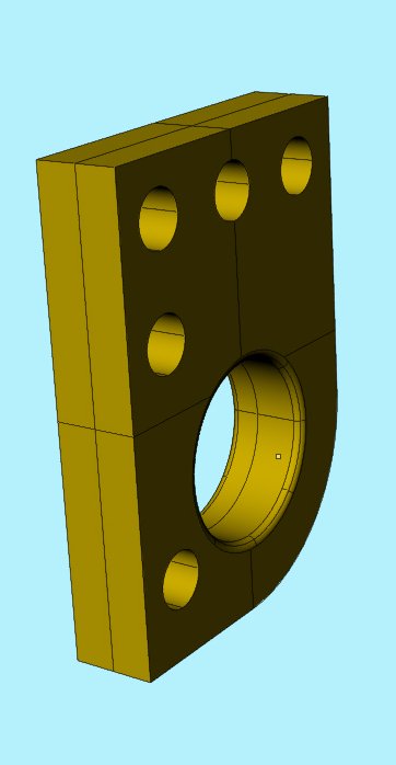
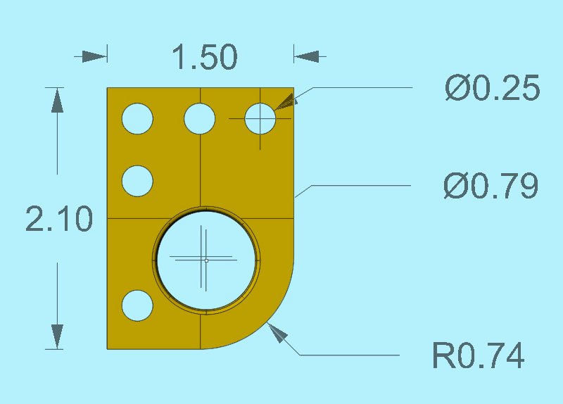
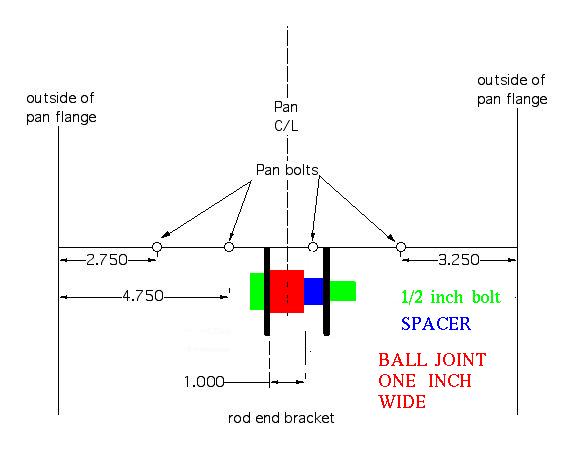
oil pan, what kind of dimensions and rubber bushings do you use there?
Don Mitchell
I don't know the answer to that question. Perhaps there is some info that
in the plans. If you have the plans perhaps you can scan the relevant parts.
We have limited options on the rear RV10 mount because the large nose gear
rubber bushing mount must be supported by the motor mount. There are fore
and aft loads on this cup when the nose gear contacts the ground. Therefor
we need two tubes going forward feeding the loads in to the joint between
upper and lower main diagonals. I marked up this jpg to show those tubes.
The proportions will change when we get better info on the cowl.
This means we will wind up with something near identical to Bobby's
rear motor mount using another Barry rubber mount.
Paul Lamar
The Rotary Engine NewsLetter. Powered by Linux.
ACRE NL web site.
http://www.rotaryeng.net
Youtube key word PaulLamar2
Copyright 1998-2009 All world wide rights reserved.