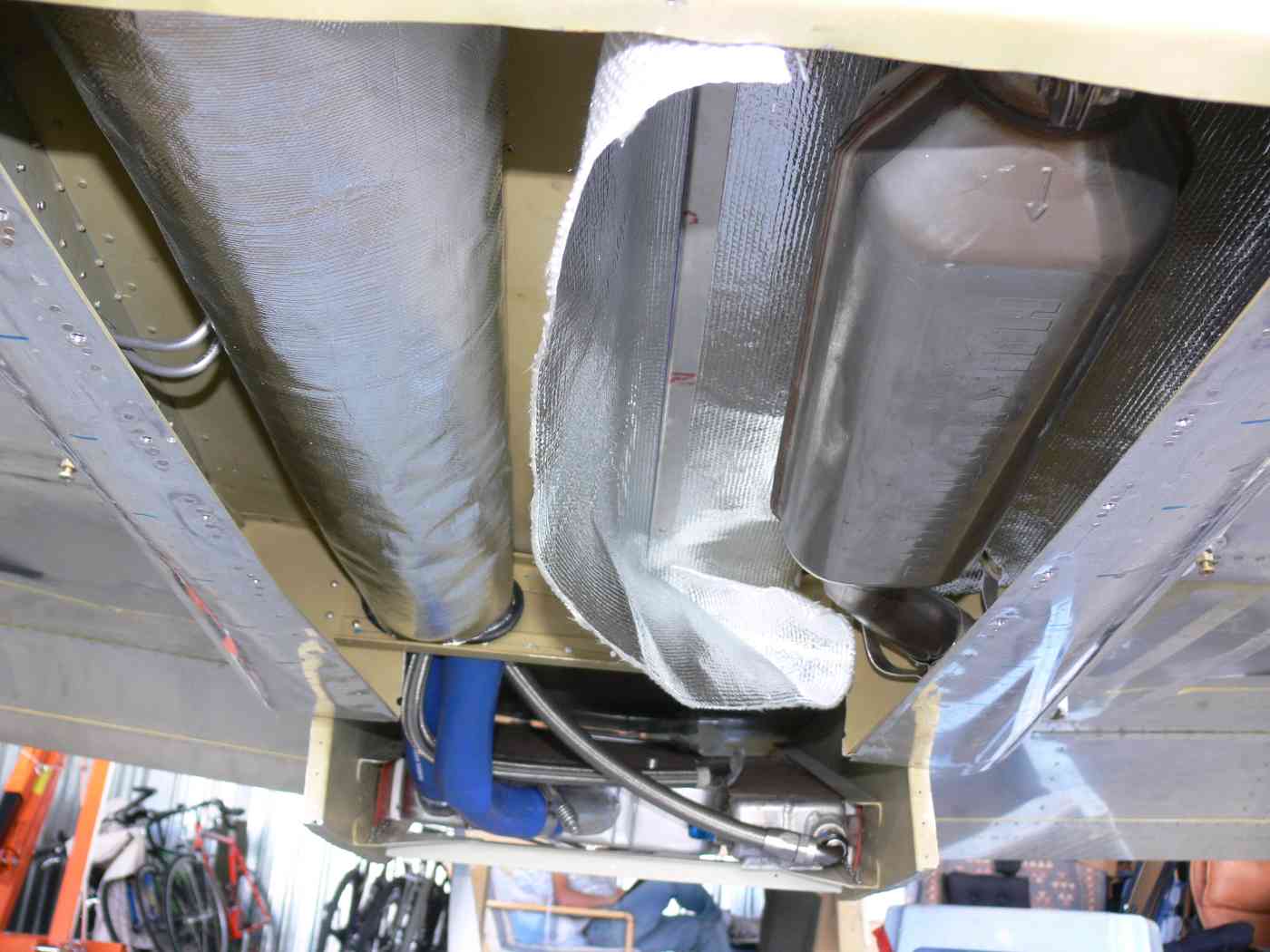
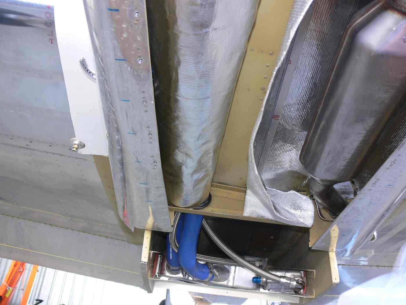
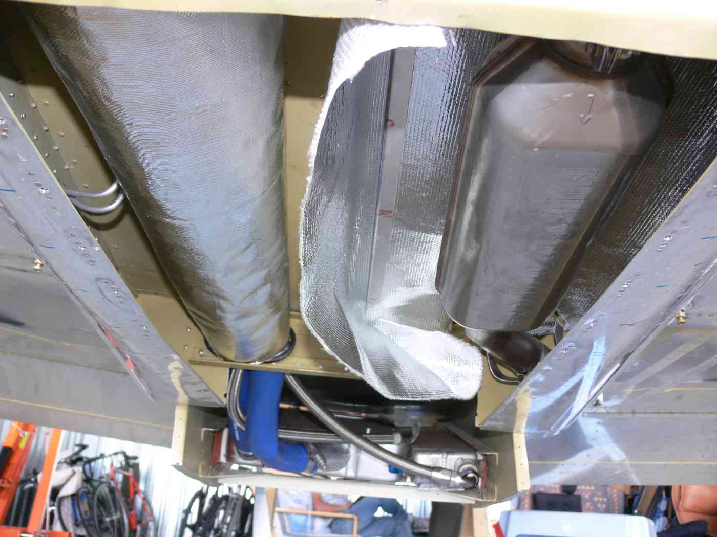
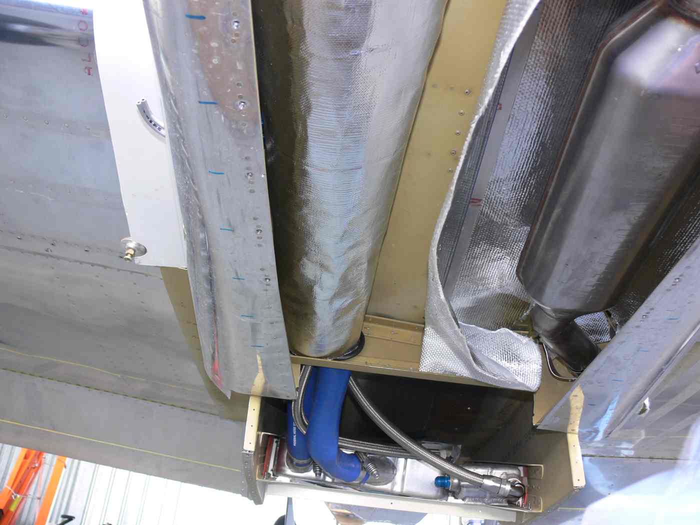
Here are a few photos of the air scoop, which is still in progress. The
side shot shows the exhaust outlet and the inner part of the scoop.
There are some aluminum panel pieces which complete the outter part of
the scoop, they are not installed in this photo.
There is a shot or two from the rear showing the outlet of the heat
exchangers. On the left is the oil cooler, and the griffin radiator is
on the right. I intend to put a large cowl flap there, hinged at the
bottom and operated with a linear actuator.
Looking at the interior of the scoop from the front, you can see that I
have to do some streamlining to smooth the flow inside the scoop. I
don't think that will be too problematic.
Brian Trubee
I would forget the cowl flap. It could easily hurt rather
than help. Fly it with out it for now.
When you have the scoop off please take a few more picture
from a 3/4 view. I cannot see that much straight on.
I suspect you will need a boundary layer bleed like a P-51
but maybe not. Build yourself a water manometer and check
the pressure above the rad when you are running it up
on the ground with the tail anchored.
Paul Lamar
--
The Rotary Engine NewsLetter. Powered by Linux.
ACRE NL web site.
http://www.rotaryeng.net
Youtube key word PaulLamar2
Copyright 1998-2009 All world wide rights reserved.