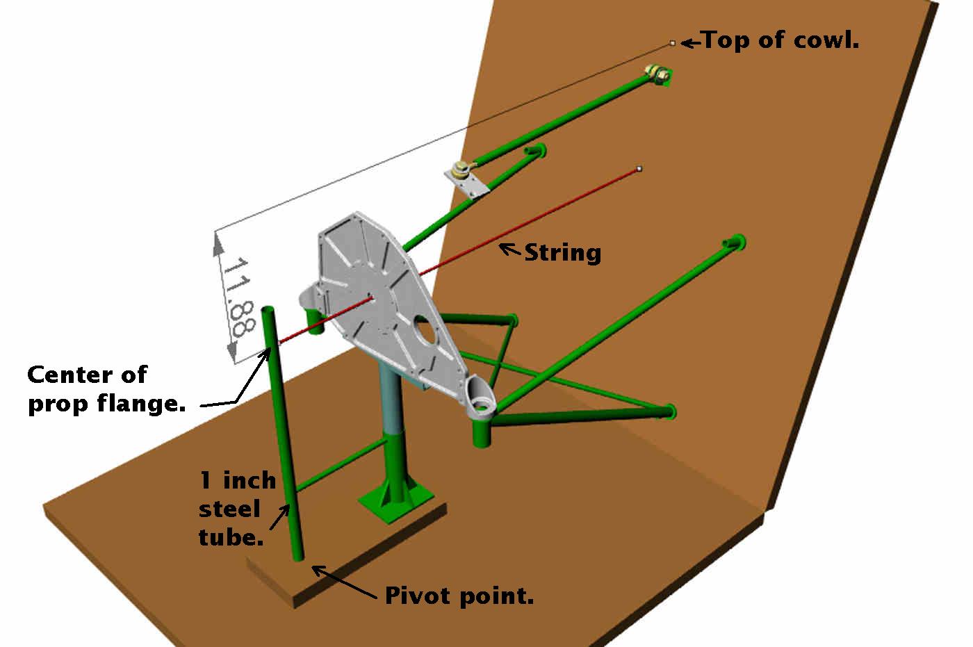
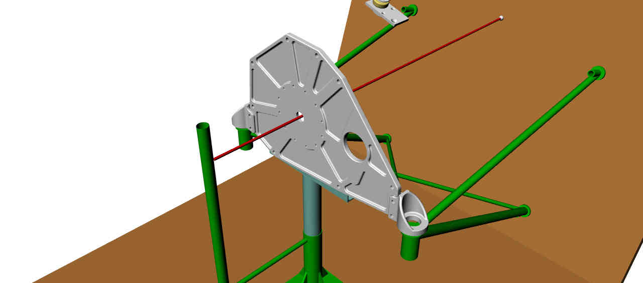
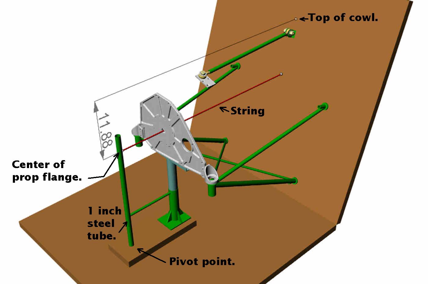
The idea here is to set up a point on the MM jig
that corresponds to the center of the prop flange
in the cowl hole.
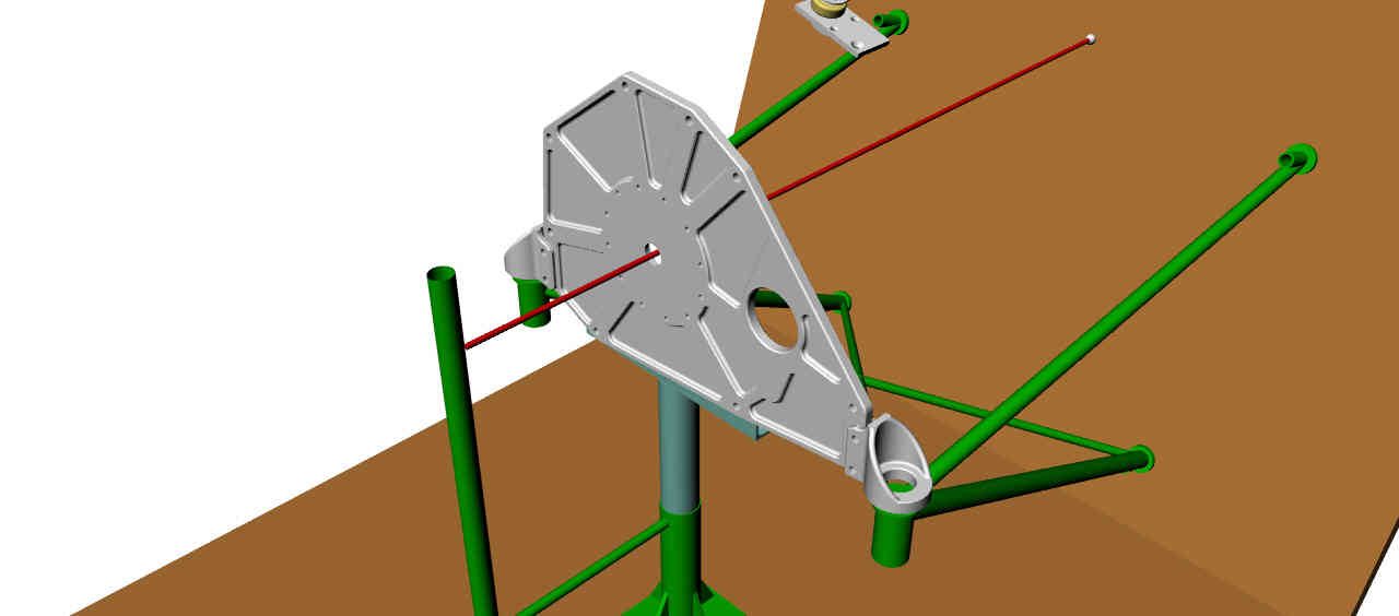
Run a string back through the center hole on Jeff's
motor mount plate to the firewall. The angle of
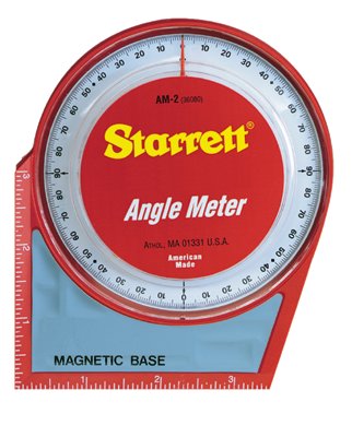
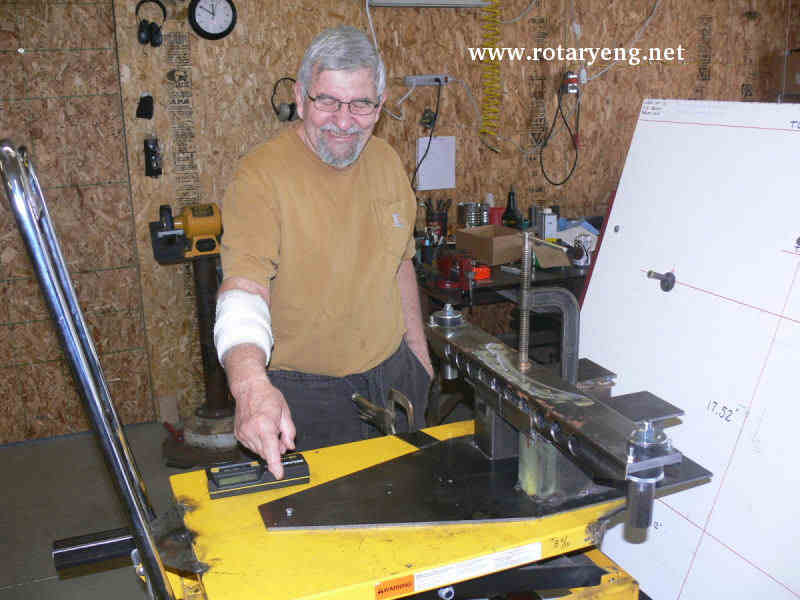
the string relative to the horizontal will be the
down thrust angle if any. You will have to adjust
the plate up and down to get the hole in the center
of the string. You will then have to tilt the plate
forward at the down thrust angle.
You will also have to rotate the
front movable part of the jig around the pivot
point to set the side offset angle.
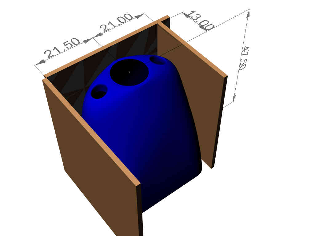
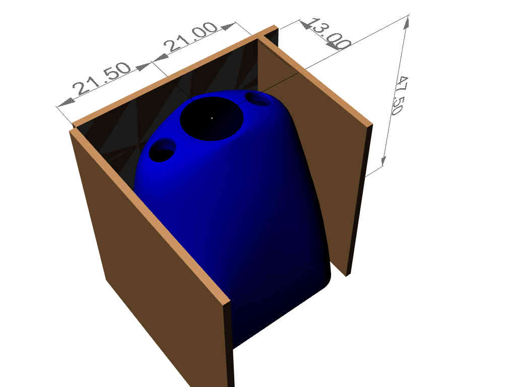
The information you will need to build a motor mount
from a kit plane is the position of the hole in the
cowl relative to the firewall. Unfortunately
this information is not given on the plans so you
will have to measure it. Here is a JPG that shows
how to do that.
If you are building your own cowl some of these steps
can be avoided as you will fit the cowl to the installed
engine.
You will also need the down thrust angle if any and
the offset angle if any.
With that info you can set up a jig to build an
accurate motor mount that will result in the prop
flange coming out in the center of the cowl hole.
Hopefully someone will build a jig and offer to
build motor mounts saving you the time.
Paul Lamar
--
The Rotary Engine NewsLetter. Powered by Linux.
ACRE NL web site.
http://www.rotaryeng.net
Youtube key word PaulLamar2
Copyright 1998-2009 All world wide rights reserved.