Hi Paul-
I've been staring at the PPort install, wondering how to modify the
oil cooler install I currently have (if I end up needing to). One of
the things that strikes me is how much interference is caused by the
engine mount tubes in the S-Beam configuration. They're everywhere,
and can make it quite a challenge to put other components (e.g., oil
coolers) where you might want them. Not that I have any intention of
making sweeping changes to my install, but it got me thinking.
It occurred to me that simply reimplementing the 13b front cover might
allow for a design that was dynafocal friendly -- without trying to
mess with more complex engine parts (e.g., end housings) -- might be
possible. I note that in a recent posting there were Rhino drawings
that had Dynafocal in their names that are probably along the same
lines of thinking.
Following this chain of thought, I have two concerns about the
robustness of this type of solution:
1) The 13b engine tension bolts (and by extension the Renesis bolts as
well) have been known to fail in aviation applications simply from
vibrational fatigue. This is acceptable (in so far as the engine
keeps working) when the engine has forward and aft mounts. In the
cantilever mount approach, I wonder whether we would see accelerated
failure of the tension bolts & am concerned about the in-flight
consequences of the tension bolts letting go like a zipper.
2) The front cover (aft in aviation install) is not attached via the
tension bolts, but rather through a series of taps in the end housing.
All the tension from the cantilevered engine (6g hard landing), as
well as the torsional loads from the engine making power will be
concentrated here. Even assuming one increases the size of the end
housing to incorporate the pads for the water pump, I wonder whether
these (2cm deep?) taps would be up to the job over a notional 2000 hr
tbo.
Interested to hear your thoughts.
Mark (Rocky Mtn High)
I agree with you and the MM loads are real high. The Lycoming
engine itself is obviously designed to take the loads.
In Mistral's case they are making all the engine parts
so they have the opportunity to beef them up to take
the cantilever engine loads if a problem appears. In the case
of the Le Mans race cars, where the engine was a stressed
member of the chassis, carbon fiber sandwich plates were added at the
top and bottom of the engine to beef it up.
Since Jerry built your mount we have gone to an asymmetrical MM design
giving more room in the engine compartment for cooling systems.
The water rad can now be mounted vertically on the cool side of the engine
and a larger oil cooler underneath.
In your case here are some suggested improvements to your oil
cooling system that can be done with out major changes.
I think these changes will be a major help.
Don't worry about the drag of the cowl flap
when open. It will have near zero effect on the climb
rate. Climb rate is 90% power to weight ratio.
1500 FPM climb is 25 feet per second straight up.
25 times the gross weight of the airplane is the
net HP out of the prop needed to lift that amount of weight.
The net HP is therefore 50,000 pound foot per second
or 90 HP out of the prop alone not counting induced drag
due to lift just to lift the weight of the aircraft.
At best the prop is 80% eff. so that means
you need 112 HP out of the engine just to lift the
weight of the aircraft. At your density
altitude your engine is down on power to about
75% so total engine power is about 187 HP.
Net out of the prop is only 150 HP at your density
altitude.
BTW There is nothing that can be done about induced
drag due to lift short of increasing the span.
Paul Lamar
Rocky Mtn High, Just a few thoughts about dynafocal mounts and tension
bolts. There are actually two similar appearing traditional aircraft engine
mountings. The dynafocal and the conical which are distinguished by the
point at which the angled pads of the four bolt flange meet like the focus
point of a lens. In one case the newer dynafocal type point to the center of
the prop disk while the conical point to the center of gravity of the
engine, prop, and any other weight outboard of the rubber bushings. A four
bolt flange is occasionally used on ultralights where the four points are
parallel with no intersection.
Reguarding the tension bolts the problems are related to fatigue
breakage at the root of the last thread caused by harmonics of the engine
and the resonant frequency of the part. The original fix was to put RTV on
the bolt shank to reduce the movement laterally. A second less messy choice
was to slide a wrap of plastic sheating around the bolt shank which is
difficult because the holes in the side housings are smaller machined holes
than the cast holes of the rotor housings. Also the center locations and
diameter of individual cast holes in the rotor housings is not consistant.
The approach I want to try is machining "O" ring grooves in the center
housing which will crush around the bolts. The downside of the "O" ring
solution is that the small amount of coolant flow thru the bolt to rotor
housing clearance would also be eliminated. Personally I don't see this
concern because the pressure at both ends of the hole are nearly the same
and no flow would be present.
IMHO the tension bolt strength is not a concern for the dynafocal
approach based on logic. The thrust load from the prop devided by the
number of bolts is a minimal strain and the addition of a 6 G landing is
dampened somewhat by the mounting bushings. In the event of an aerobatic
installation the gyroscopic loads are enormous and the bed mount derivatives
look best for a rotary. After my original end housing design I did some
research on other aluminum end housings and noticed a similarity. The Racing
Beat housings included external tension bolts just above the oil pan rails
as can be seen on the picture of the 109 pound core engine posted last week.
The original Mistral tried a dynafocal mount off the front cover but
discarded that approach on the Beta test engines. Their next iteration
cast the dynafocal mounting into the front side housing and added four
external tie rods from the front housing to the PSRU casting. The external
tie rods being farther from the center of the the engine resist the leverage
of the external loads more effectivly than the tension bolts. Thes engine
mounting and tie rod changes are easy to implement in a new design and
impossible to add to the existing castings. As Paul has pointed out the 2.85
multiplication of prop torque from the PSRU and shortening the load path
from gyroscopic loads make mounting from the bellhousing end prfereable and
with the PSRU plate available from Jeff there is no need to reinvent the
wheel.
The problem with putting mounts on the accessory housing is the
small number and size of the attaching bolts. Adding additional bolts to the
relatively thin front housing face wouldn't have any bearing area to pull
the proposed accessory housing down to. It would be possible to add external
tie rods from such an accessory end cover back to the PSRU plate for the
tension loads but there is no good way to counter engine torque. Someone on
this newsletter is working on an accessory cover which has the oil pan
adding attachment and torque reaction. I suggested he might add some sheat
metal brackets from the back of the cover back to the car motor mount holes
to stiffen up this arrangement.
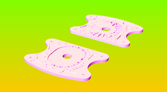
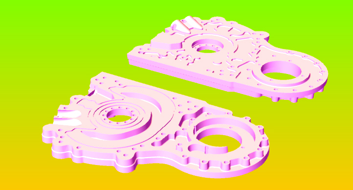
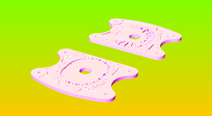
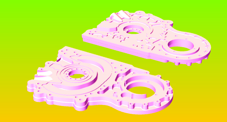
I am going to attach a JPEG of a dynafocal type mount drawn in
Rhino. This piece as well as 19 other parts consist of a two piece side
housing with an "O" ring sealed joint. The plan is to have two open face
parts which could be CNC machined and bolted together to make side housings.
I was intending to use a cast nickel iron nitrided part for the rotor
side with the remainder of the housing done in magnesium. Current plan is to
use 390-17 aluminum as used on Vega cylinder blocks, pistons, and Briggs and
Stratton since 1984 which has the silicon carbide as nodules in the
aluminum. It is stronger than other casting alloys and doesn't need
additional wear surfacing. This material is time consuming to lap but
doable. All parts in this set have provision for four 1/2"external tie rods
as an option. The use of the 390-17 requires a casting so I also did the
casting patterns. I will ger a copy of everything to Paul shortly saved in
Rhino, Solid Works STL and Igs formats in case anyone has any interest.I
think I will also try to attach the outside part of a stock type front
housing to show how the two parts are related. The JPEG images are a top and
a bottom view of the same part. The side that faced the rotor housing is
recognisable by the coolant passages. This part is P-port only, there is a
separate set for the eight port engine.
george grimes
--
The Rotary Engine NewsLetter. Powered by Linux.
ACRE NL web site.
http://www.rotaryeng.net
Youtube key word PaulLamar2
Copyright 1998-2009 All world wide rights reserved.