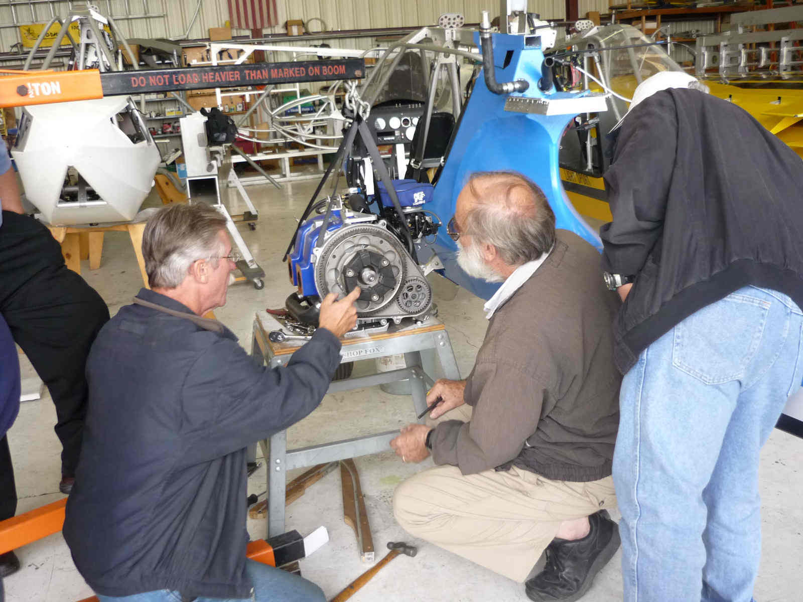
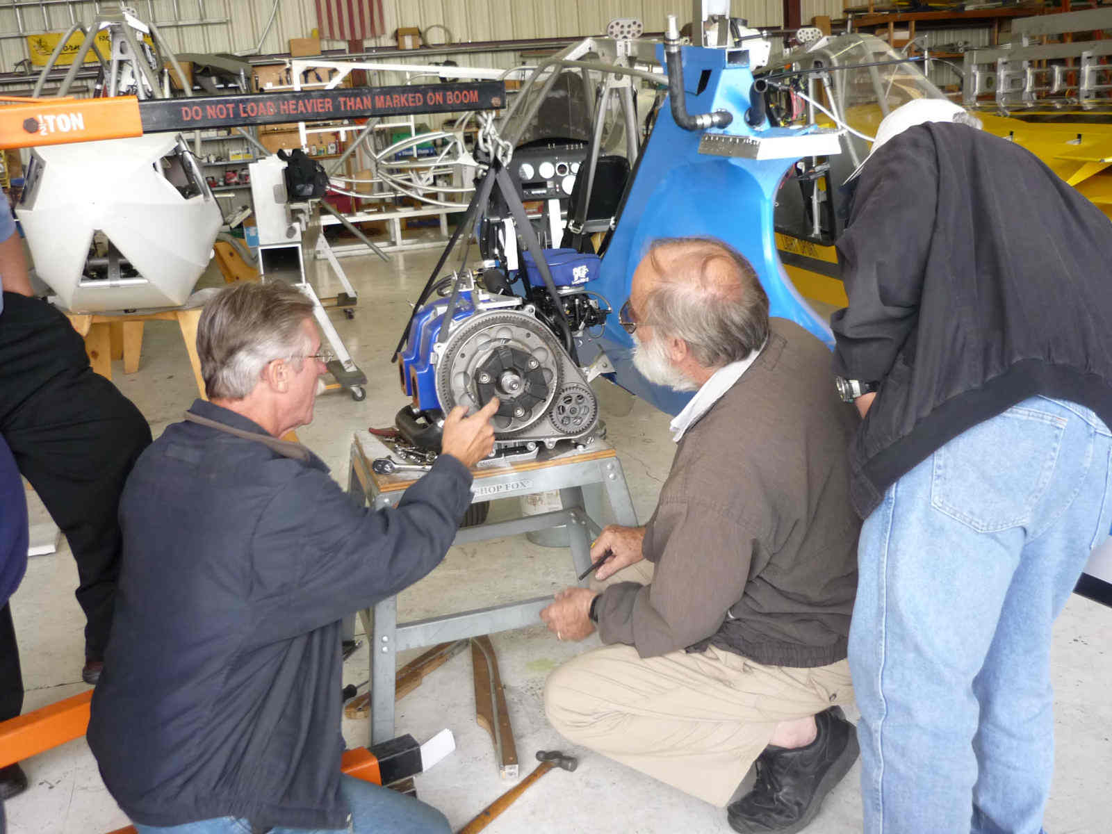
Somebody brought this to my attention at Sun N Fun.
NTSB Identification: CHI08LA274
14 CFR Part 91: General Aviation
Accident occurred Wednesday, September 03, 2008 in Findlay, OH
Probable Cause Approval Date: 3/23/2009
Aircraft: Sadler Vampire, registration: N333SV
Injuries: 1 Minor.
The airplane was an experimental amateur-built airplane that was a prototype for light
sport aircraft certification. The flight test was conducted by the engine manufacturer,
who also provided a pilot to fly the airplane. The pilot had not received flight
instruction or a checkout in the airplane. The pilot learned to fly the airplane on his
own by taxiing and performing local flights in the airport area. The pilot also had no
training or experience in aircraft flight test. A larger radiator had been installed onto
the airplane due to noted high engine temperature during previous flights. Prior to the
accident flight, the pilot performed two taxi tests during which he performed short hops
on the runway to get familiar with the aerodynamic forces that would be encountered during
takeoff and landing. The engine temperature was reported as normal during this time. The
pilot then attempted a takeoff for a flight that was to remain in the airport traffic
pattern. Just after takeoff the airplane lost total engine power. The pilot attempted an
engine restart without success, during which he did not hear the engine turn over. The
pilot then executed a forced landing into a quarry located about 0.6 miles from the
departure end of the runway. An examination of the reduction drive assembly needle roller
bearing sidewall revealed a combination of wear and high temperatures leading to
overstress. Circumferential wear marks on the separated cage sidewall and the presence of
metallic debris suggested impingement of the rollers on the sidewall during engine
operation. Heat tinting of the outer raceway in the vicinity of the failed sidewall and
the cam that served as the inner raceway was also noted. The needle bearing malfunction
could be attributed to misalignment of the needle bearing and insufficient lubrication.
The National Transportation Safety Board determines the probable cause(s) of this accident
as follows:
A total loss of engine power due to the failure of the reduction drive assembly as a
result of excessive wear and high temperatures. Contributing to the accident were the
pilot's lack of total experience in the airplane and the unsuitable terrain for a forced
landing.
CHI08LA274
On September 3, 2008, at 1257 eastern daylight time, a Sadler Vampire, N333SV, received
substantial damage on impact with terrain during a forced landing and a post crash fire.
The airplane experienced a total loss of engine power after takeoff from Findlay Airport,
Findlay, Ohio. Visual meteorological conditions prevailed at the time of the accident. The
14 CFR Part 91 flight test was not operating on a flight plan. The pilot sustained minor
injuries. The local flight was originating at the time of the accident.
The airplane was certified as an experimental amateur-built airplane and was used as a
prototype toward seeking certification as a light sport aircraft by its manufacturer.
The pilot stated the engine previously experienced "slightly" high engine temperatures
that had been reduced to the "normal operating range" with the installation of a larger
radiator onto the airplane.
The airplane was fueled from a portable fuel tank in the back of a pickup truck. This fuel
tank did not have any sump drains or fuel filtration available. The pilot stated that
there were no fuel sump drains available on the airplane and Federal Aviation
Administration (FAA) inspectors did not note the presence of any fuel sump drains during
their post accident examination of the wreckage. Additionally, the provided airplane
checklist did not mention the sumping of fuel to check for contamination.
The pilot performed a low speed taxi followed by a high speed taxi. He performed "short
hops" to get used to the aerodynamics of the airplane for takeoff and landing. He then
"felt confident" that everything was operating "well" enough to fly the airplane one time
in the airport traffic pattern. The pilot used runway 07 (5,883 feet by 100 feet, asphalt)
for the takeoff. He applied full throttle and obtained an engine speed of 5,100
revolutions per minute (rpm). He rotated the airplane at 65 miles per hour (mph),
maintained 75 mph, and obtained a climb rate of about 200 feet per minute. He turned
crosswind approximately 500 feet agl, and in the turn to the downwind leg, the engine
experienced a loss of engine power while over Main Street. He attempted an engine restart
but did not hear the engine turn over. He then turned his attention to executing a forced
landing. He pitched the airplane to obtain 85 mph, which reportedly was the best glide
speed. He stated that the glide ratio was "very poor" and knew that he could not return to
the airport. He saw a quarry that he thought was his best option for a landing area
because of the commercial area adjacent to the airport. Once he knew that he could reach
the quarry, he allowed the airplane speed to increase to about 95-100 mph. As the airplane
descended, the ridges in the lower part of the quarry, where he wanted to land, came into
view. The airplane inadvertently touched down on the first ridge and bounced. The pilot
wanted to avoid a stall so he pitched the airplane nose down. He then impacted a second
ridge with trees and the airplane yawed left. He was unable to realign the nose of the
airplane with the direction of travel. The airplane touched down and slid to a stop.
According to the Findlay Police Department Report, the airplane's main landing gear wheels
touched down on an upper ledge of the quarry and bounced off the edge before striking two
small trees and a lower ledge in the quarry. The airplane's nose landing gear then struck
the bottom of the quarry. The airplane travelled westbound an additional 135 feet before
coming to rest. The pilot exited the airplane, and the airplane then caught on fire.
The airplane wreckage was located approximately 0.6 miles north from the departure end of
runway 36.
The pilot, age 24, held a commercial pilot certificate with single-engine land,
multiengine land, and instrument airplane ratings. He was issued a flight instructor
certificate in May 2008. He accumulated a total flight time of 455 hours, 6 hours of which
were reported in the make and model of accident the airplane. The pilot stated that he was
hired by his brother-in-law, who was the engine manufacturer, as a test pilot which was
also a way for him to accumulate flight time. The pilot stated that he did not receive an
airplane checkout in the accident make and model airplane but learned to fly the airplane
on his own. He stated that he got used to the airplane on airport taxiways and on flights
limited to the airport area. The pilot had no previous aircraft flight test training or
experience.
The aircraft manufacturer stated that the airplane fuel system consisted of a single-fuel
tank with a sump drain located on the gascolater, which was the low point in the fuel
system. There was a metal to metal fuel shutoff valve, and excess fuel was ported back to
the fuel tank near the fuel tank vent. The fuel cap was not vented.
Cockpit engine water temperature indication is sensed at the outlet side of the engine
cooling system prior to entering the radiator.
The airplane was powered by a Rotamax 1300CG engine at the time of the accident. The model
and serial number of the engine were obtained from company provided records that stated
the engine was serial number 5, manufactured on October 15, 2007, and accumulated 52
hours. However, the Affidavit of Ownership for Experimental Aircraft, AC Form 80850-88,
identifies the engine as a Rotamax R700, serial number 2-DC-R-S-N-G-004. The engine
manufacturer stated the Rotamax 1300CG was the correct engine model for the airplane.
Post accident disassembly of the installed Rotamax 1300CG engine and reduction drive
assembly was conducted under the supervision of the Federal Aviation Administration.
During the disassembly of the reduction drive assembly, multiple bearing failures were
noted. The reduction drive assembly was then shipped to the National Transportation Safety
Board Materials Laboratory for metallurgical examination.
The metallurgical examination revealed one end of the rotor bearing journal exhibited a
dark and discolored surface relative to the opposite rotor bearing journal on the shaft.
Light colored lines from the needle rollers were visible on the surfaces of both rotor
bearings. There were no indications of deformation (brinnelling) by the rollers on the
inner raceways. Closer examination of the discolored rotor bearing journal revealed metal
transfer on the bearing surface and pitting on one location. Similar light colored lines
from roller bearings were noted on the main bearing journals.
The complete circumference of one of the sidewalls had separated from the rest of the
needle bearing cage. Upon removal of the sidewall, four needle rollers fell out of the
cage due to damage and plastic deformation to which the cage had been subjected. It was
not apparent whether this damage occurred before or after the sidewall separated from the
cage. Small shards of metal were found on the rollers and the outer raceway. The outer
housing was discolored on the side with the fractured cage sidewall and around the oil
hole in the middle. A piece of metal debris was found inside the oil hole.
The needle rollers showed signs of abrasive wear and damage to the ends of the rollers. A
typical needle roller exhibited abrasive wear by third body particles at an end which was
adjacent to the fractured cage sidewall. The diameter of the needle roller on this end is
also reduced relative to its opposite end. A random sampling of five rollers produced an
average reduction in diameter of 0.0064 inch +/- 0.0007 inch. The ends of the rollers next
to the fractured cage sidewall were concave in profile with buildup of material around the
edge. The opposite end of the roller ends possessed rounded edges.
The fractured sidewall of the cage had concentric abrasion marks coincident with the
location of the needle rollers. In between the rollers it appeared that two fractured ribs
had been plastically deformed and pressed against the cage sidewall. In another location,
there appeared to be buildup of metal debris on the fracture cage sidewall.
Two ball bearings within the assembly had seized. The balls in one raceway of the double
row ball bearing were clustered together creating an approximately 120 degree included
angle of raceway in which there were no balls. There was no readily visible evidence that
would explain the seizure of these bearings. Most of the bearings, once wiped of residue
showed, a typical lightly scratched finish with some discoloration from heat from post
crash fire.
End of NTSB report.
Rumors at the time said it was a disconnect failure of the gear box to the prop.
The NTSB frequently gets things wrong so in this case they start talking
about the gearbox and then jump to the roller bearings in the engine like
that was the cause of loss of power. We had long discussions on the viability
of the rotor needle roller bearings with Eric Barger. It appears I was proved
right as Midwest engineers warned me about that. The rotor needles were lubed
by oil injected into the intake as this engine uses a charged cooled rotor.
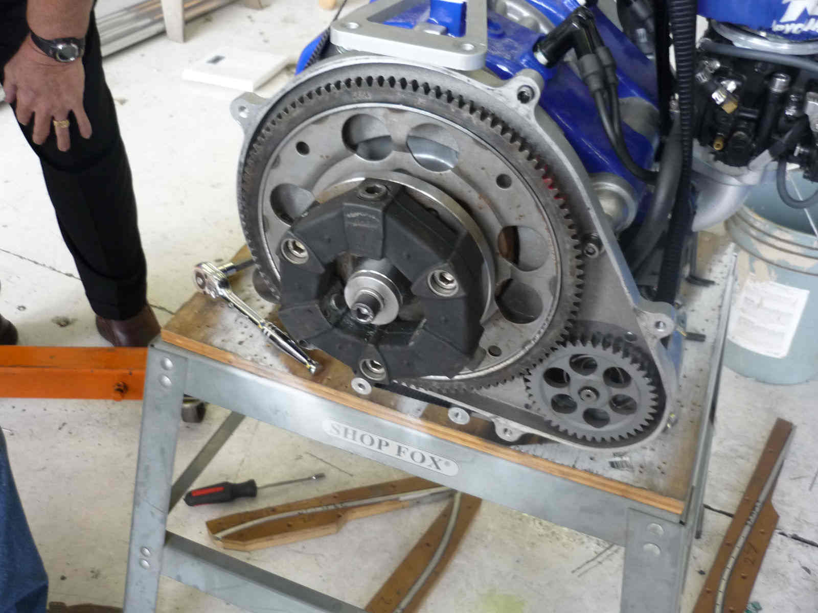
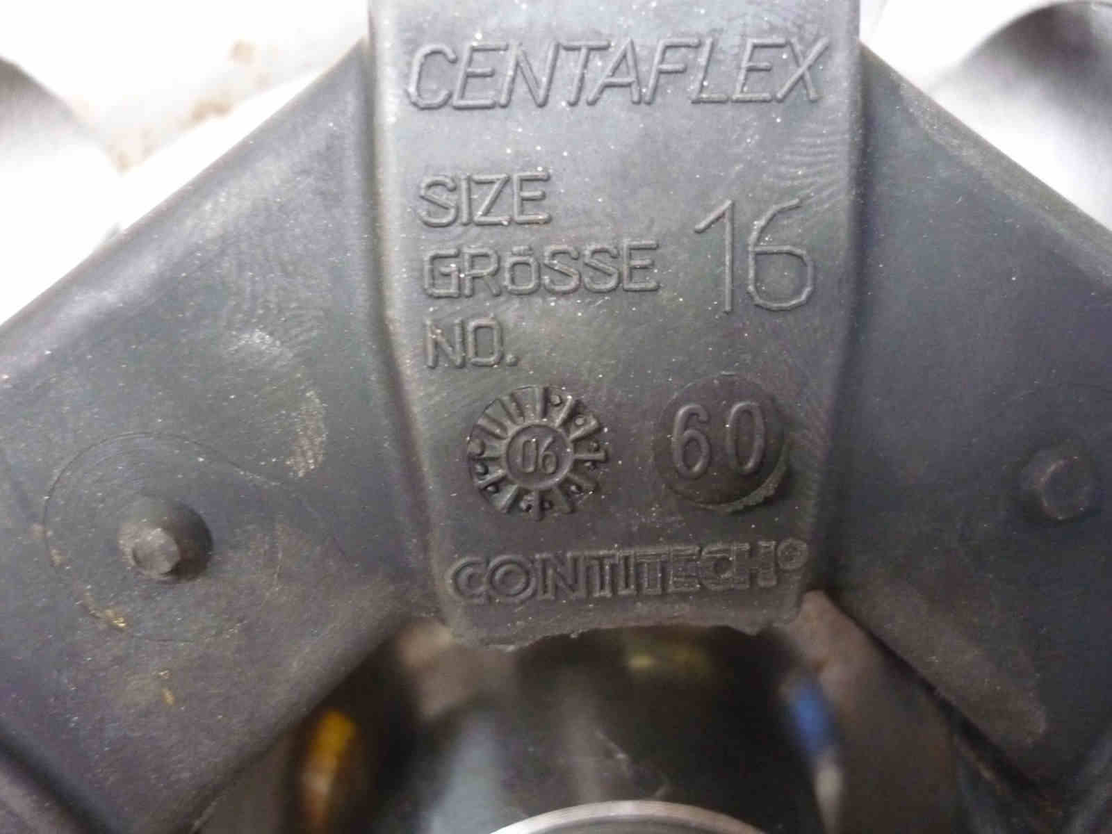
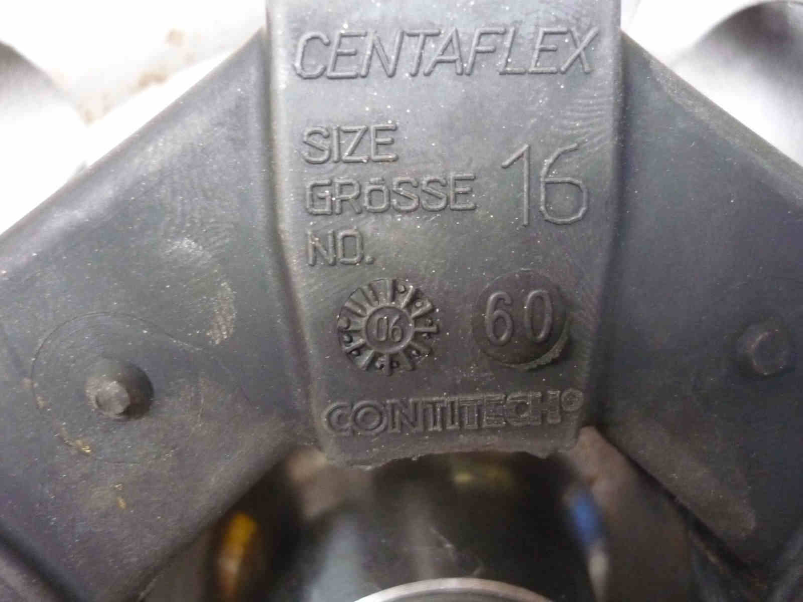
The attached picture is the roller bearing that Eric used.
The NTSB report did not say where the two ball bearings were located.
They could have been main bearings or they could have been in the gear box.
Must likely they were in the New Zealand (as I recall) built gear box.
Kind of a strange failure as gear boxes usually give a bit of warning.
This is still a mystery as far as I am concerned because I am still lacking
details on the RPM of the engine, the prop dimensions and the gear ratio
used in the gear box. Effective oiling also appears to be an issue
Can you help me out Eric?
Paul Lamar
===========================================================
Paul,
The engine was running 6000 RPM with a 2.47:1 ratio gearbox (built in New
Zealand), and a 58" prop (I believe).
The report states "A total loss of engine power due to the failure of the
reduction drive assembly as a result of excessive wear and high
temperatures"
We believe that the gearbox ran hot and that the oil failed in the gearbox,
it heated up literally creating bluing on shafts etc. this caused the engine
stoppage. After engine teardown we were "scratching our heads" as to what
happened, we dug into the PSRU and as soon as we opened it we knew where the
problem was as it appeared as the PSRU literally "blew up" inside. The ball
bearings referred to were in the PSRU and there were balls floating loosely
inside the box. We did not do the teardown on the PSRU from this initial
examination; the FAA/NTSB boxed it up and took it to their lab.
There was some heat and material marks on the rear needle bearing noted
during disassembly in front of the FAA/NTSB done by me personally, not a
cause for stoppage a noted blemish per say during the teardown.
Paul commented "The rotor needles were lubed by oil injected into the intake
as this engine uses a charged cooled rotor." The RotaMax engine actually
lubricated the rotor bearing directly from the oil injection pump thru the
eshaft, and then the oil would enter the air fuel mixture and lastly to the
Trochoid for lubricating the seals.
As you know Paul the needle roller bearings in a charge cooled engine have
always been a "Swiss watch" per say as to the required material,
lubrication, temperature and RPM. To this the charge cooled engine with a
needle roller bearing works well in varied load applications. In constant
load applications the ambient temperature along with other operating
conditions can cause an engine/bearing running on the edge of its capacity.
Several ways now to solve this concern if someone considers building a
charge cooled engine, as the simplicity of the engine is sure a value worth
pursuing. If the right design and testing were done to assure that the
engine performed well at all operating conditions with a factor of comfort
this could be a simple and reliable approach.
This should clear things up
Eric
Paul and Mark S,
The oil system was an internal bath type system with a small fill/sight
reservoir. There was no oil pump or external components other than the small
reservoir. We did not do much as to work on the PSRU we bolted them up and
began testing on the ground, on a stand and then in the aircraft. The lesson
we learnt here is that you can test engines and PSRUs on dynos, stands etc
but until the real application testing is done it is still a potential
mis-match that causes failure. This usually plaques a lot of product
attempts as the continued testing and validation costs are usually not
supported especially in start up mode. To me this is the most important time
to do it right. A costly lesson where in the RotaMax case the more money
spent on testing would have validated the problem in a less exposed
application.
BTW My son in law was flying the plane so we surely had a level of comfort
and confidence in our previous testing efforts.
Eric Barger
--
Paul and Eric,
Could the gear box failure have been caused in part by the wicked torque pulses of (any)
rotary design? I know of another failure using an Axro and Rotax C gearbox. My
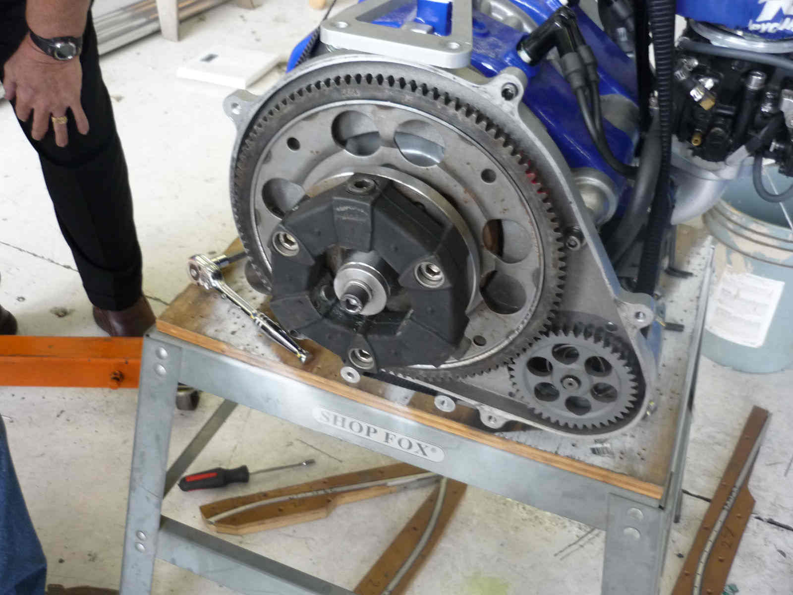
Autoflight gearbox (on a Subaru) has a rubber biscuit dampner. Could a harmonic vibration
have contributed to this failure with helical gear design? (as Tracy found out with his
design and fortunately solved) Is there an easy way to check for harmonic stresses?
Dan F
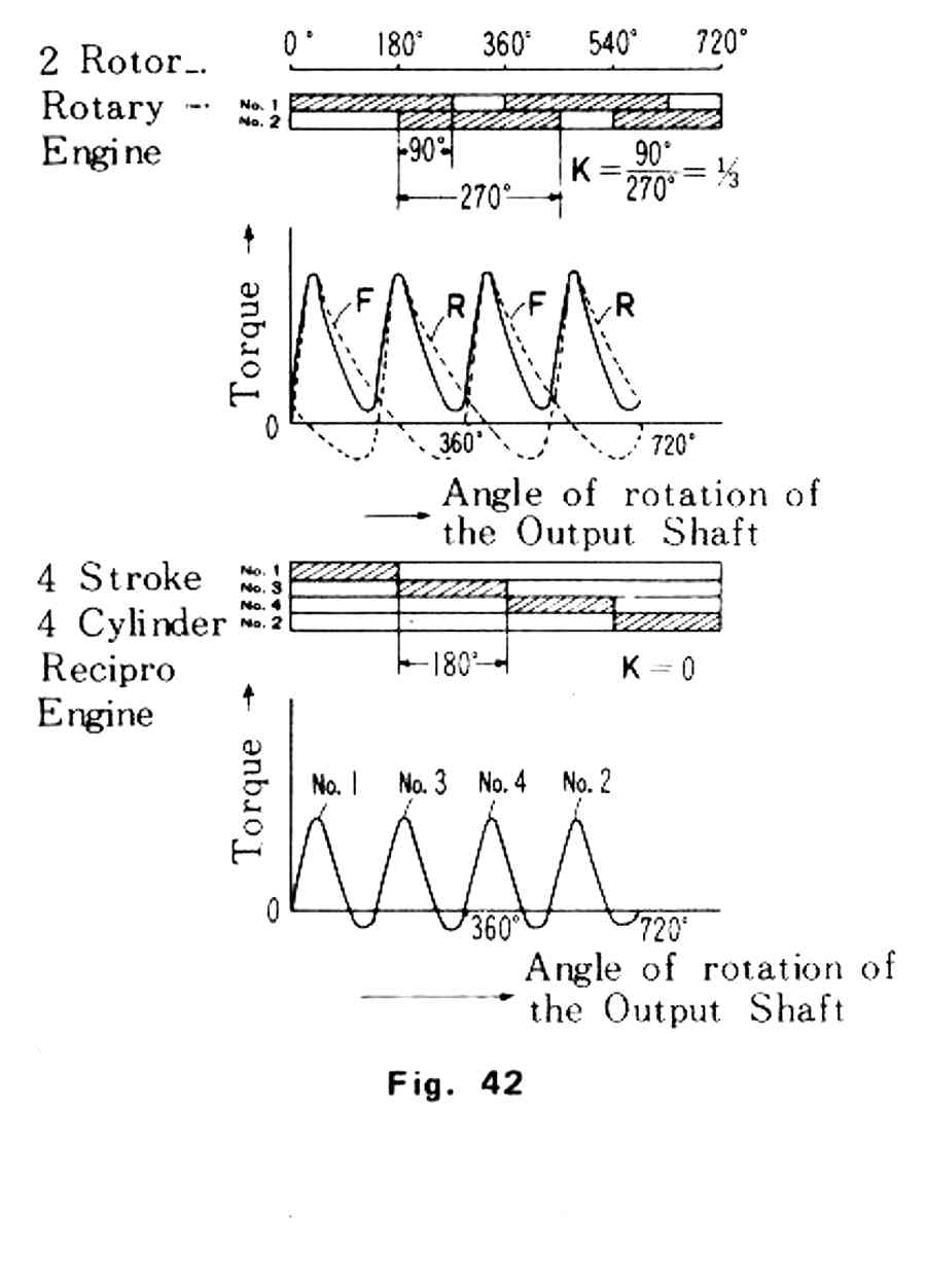
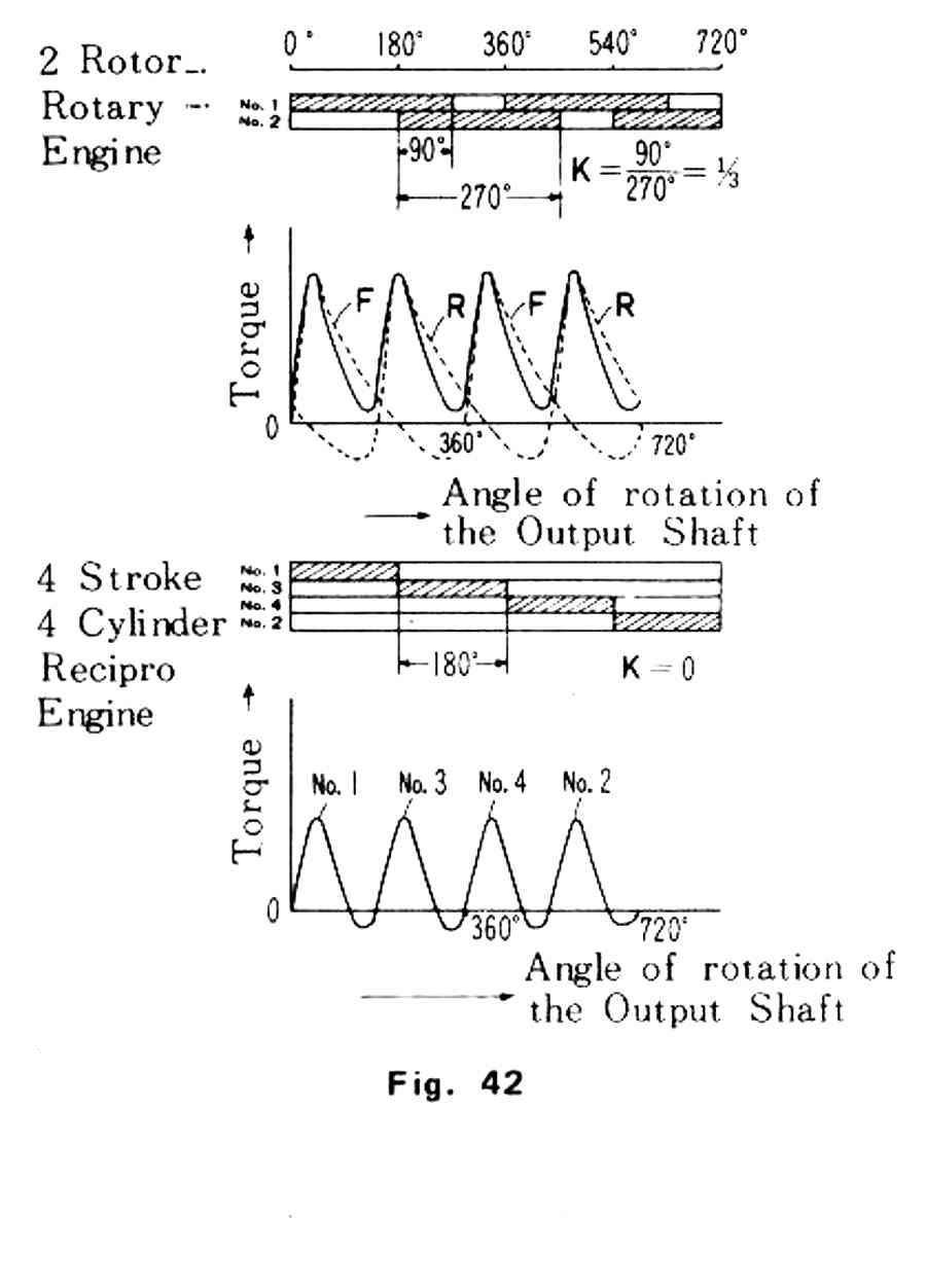
Not likely as the rotary torque pulse are more benign than a 4 cylinder four
stroke piston engine or a two cylinder two stroke engine. Note the 4 cylinder
4 stroke goes negative but the rotary does not. Severe rotary torsional
vibration is a myth. The only difference compared to an aircraft
engine is the RPM is twice as high.
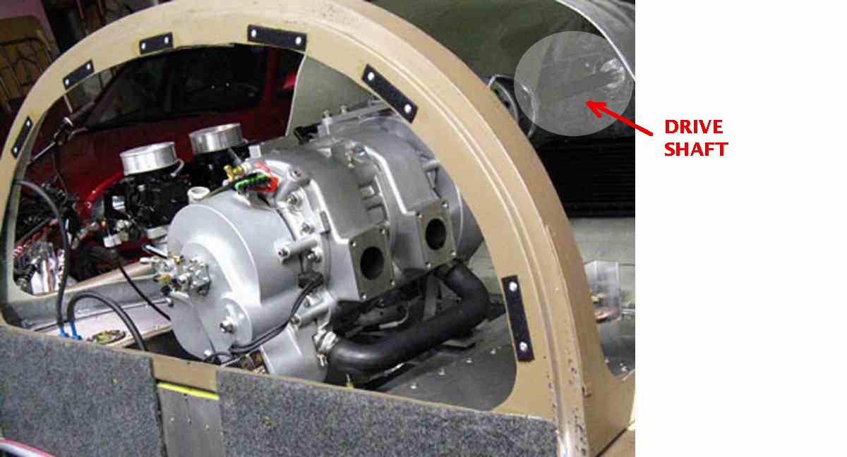
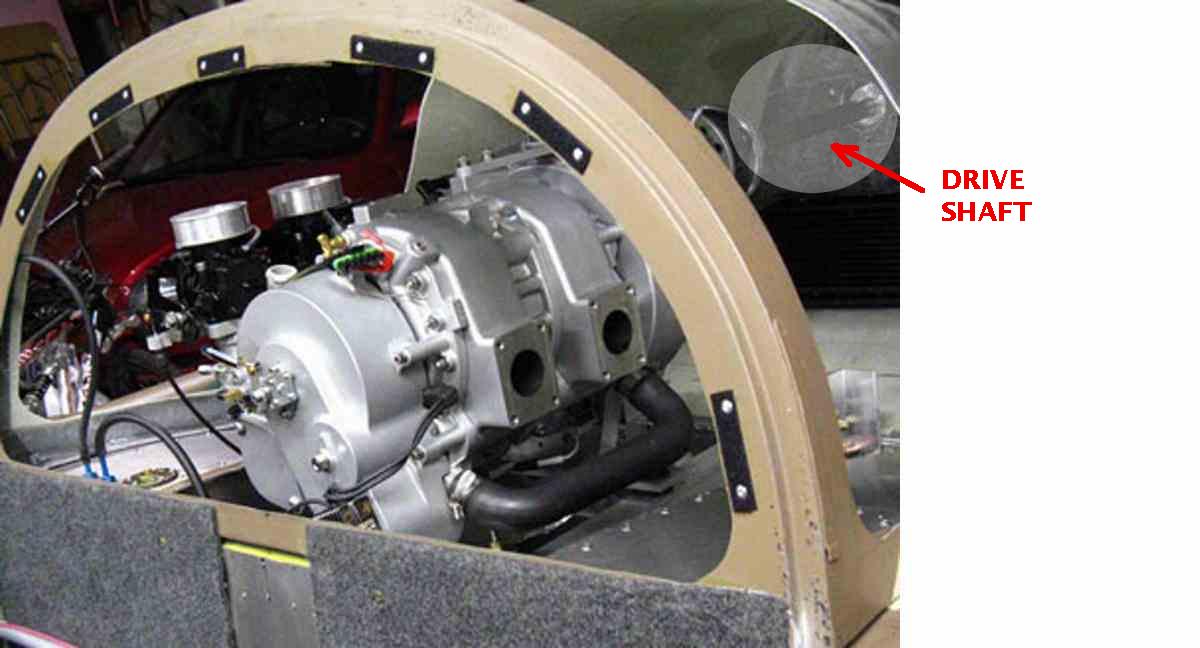
It probably had more to do with the length and small diameter of the
drive shaft from the gear box to the prop. It would have been
much better off with a 3 inch diameter carbon fiber shaft.
However inadequate gear box oiling seems to be the main culprit.
What Tracy found out had nothing to do with torque pulses.
It had to do with the thrust developed by a helical gear.
Tracy first gear box destroyed the thrust bearing in the Mazda.
If anything helical gears are stronger than spur gears.
They also have little to do with harmonic vibration.
Tracy used a rubber torque isolator right from the start.
So did Ross but it was a clutch disk center with steel springs.
The rubber torque isolator in the GB used with the Rotomax was a
bit stiff so High Class Aviation bought one with lower
durometer and installed it in the New Zealand built gear box.
That lowered the resonant frequency from about 2000 RPM
idle to about 1850 RPM idle. That however was a direct
drive prop mounted on the gear box and not shaft driven
like the Vampire.
Paul Lamar
--
The Rotary Engine NewsLetter. Powered by Linux.
ACRE NL web site.
http://www.rotaryeng.net
Youtube key word PaulLamar2
Copyright 1998-2009 All world wide rights reserved.