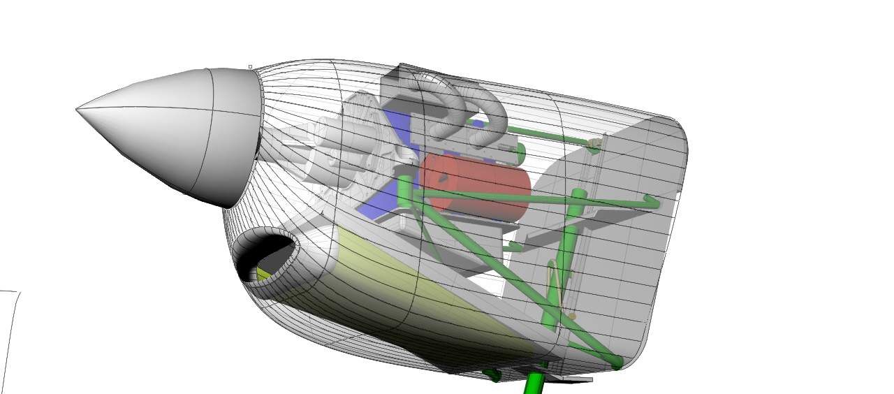
Paul, I have had some time to get back to my CAD education with Alibre.
I'm working out the cowl profiles, and was wondering if you had some
simplified models of
the 13b in combination with the RD-1c and Doddridge plate. I was hoping
to
kinda stick
them in to make sure everything clears. I'm using the extended mount
dimensions for the
lightweight version of the 13b on the Zenith CH-640.
C. Smith
Try some of these.
-----------------------------------
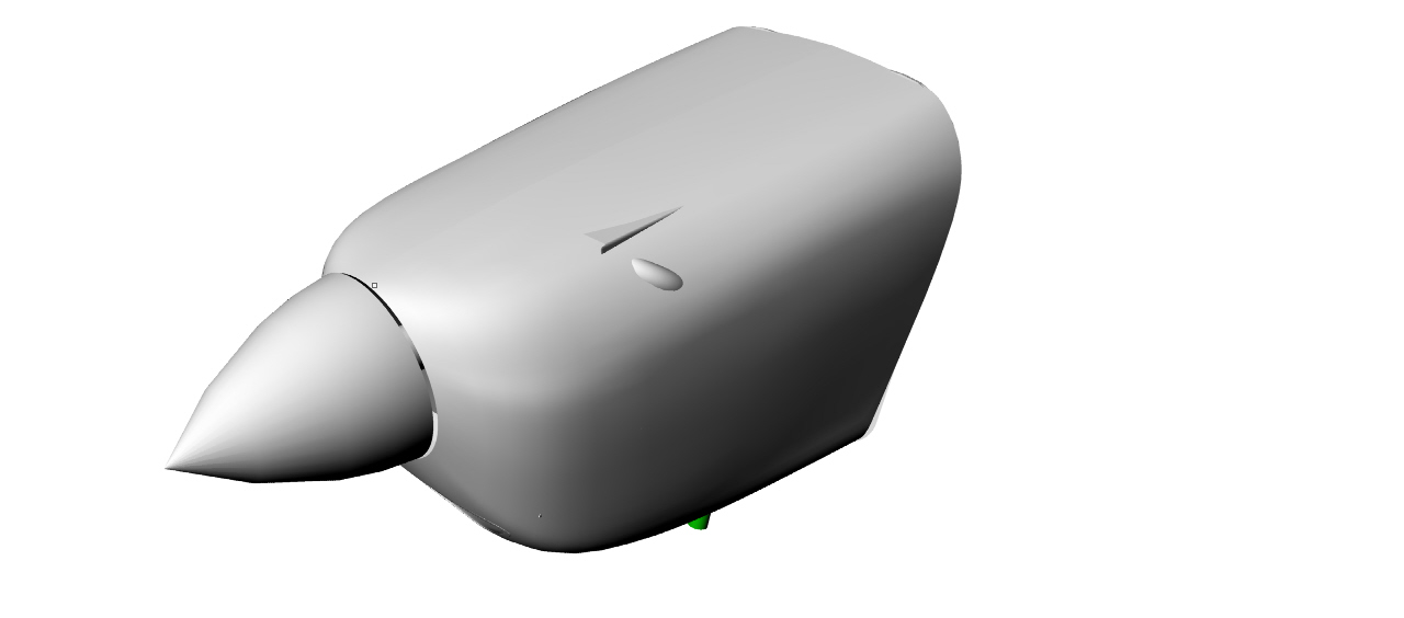
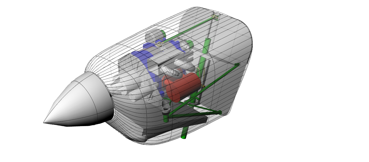
Here is what the jpgs renderings look like from that igs file I just
sent.
I have a model of your engine and motor mount.
Send me a sketch of what you want the cowl to look like
and I will send some renderings and igs if you wish.
-----------------------------------------------------
Here is the Rhino model I have.
-------------------------------
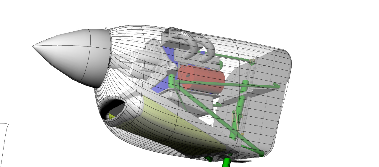
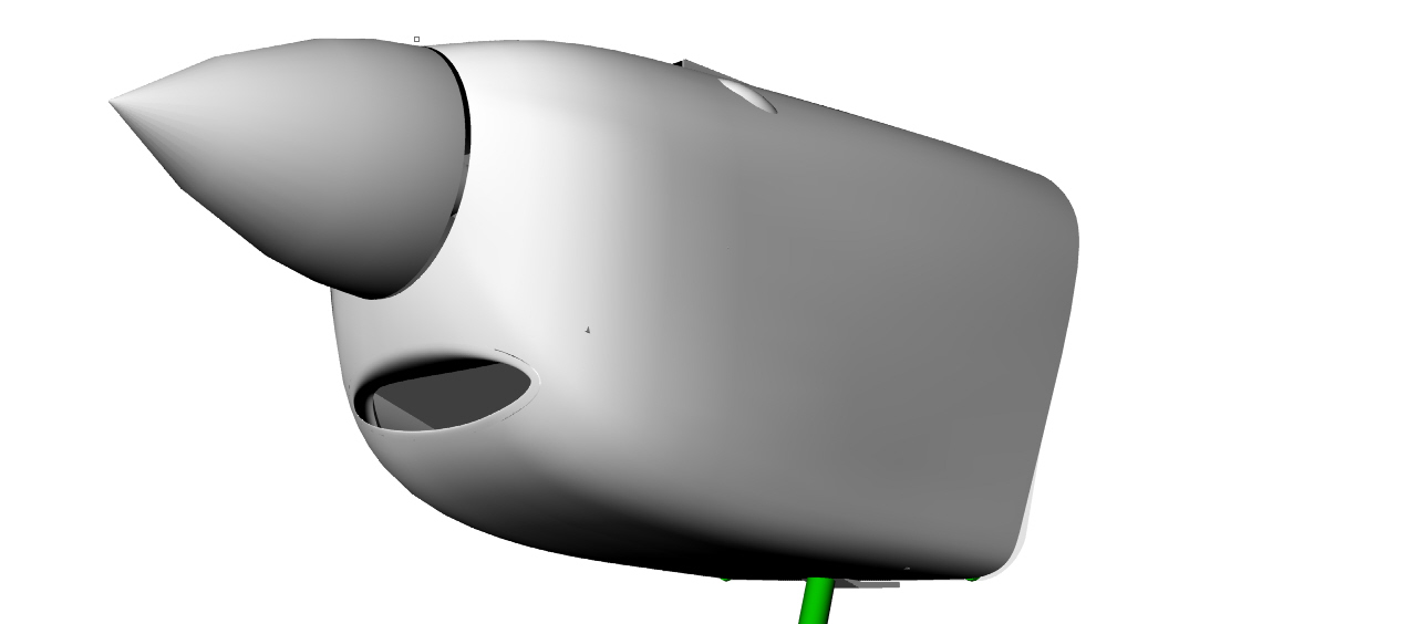
More views.
Looks like the best place for the rad
is underneath with your extended MM.
PauL Lamar
C. Smith, I am attaching a rhino file of the Mazda 13B which I got from
the
newsletter. It is dimensionally accurate and I have used it on three
fusaloge designs since I got it. You can erase any or all of the motor
mount tubes or rotate and extend them to your hard point locations.
Besides
being dimensionally accurate it does not add significantly to the drawing
file size. I saved the dimensions of Jeff's motor mount plate when it was
being reviewed on the newsletter but have not done a solid model of it.
The
attached file has a Schertz beam mount but can be swapped for Jeff's
plate
since the attached file is an assembly drawing of the individual parts
and
can be edited.
george grimes
Too big to publish George. Alibre probably won't load
3dm files anyway. Export it as igs and zip it to reduce
the size and send that.
Paul Lamar
Paul, no problem saving to Iges in Rhino 4 but I don't know how to make a
zip file. Is that some sotr of a right mouse click thing in windows
vista. If so how do I do
it.
GG
In Windows XP you click on it with the right
mouse button and choose send to compressed (zip file)
Paul Lamar
Paul, I got the 3d of the engine converted, used the default style. It
is
one of 60 igs/iges formats available. I got to the compress to zip and
e-mail page. It wanted a control panel mail icon configuration, that
didn't
recognise the web address, the new contact menu wants 12 items, none of
which anyone would have. I got this file off the newsletter so could you
possibly post it again. It was posted about april this year. If not C.
Smith
can send me an e-mail address to my yahoo mail at
george-grimes7@yahoo.com
and I can send the igs file to him as well as a JPEG of Jeff's Psru plate
with the dimensions to draw it.
george grimes
So you did not find zip in your OS?
Are you using XP or something else. This MS changing their OS
is driving me crazy. They took so much stuff out just to make more money
selling it to you later.
I sent that one already in zip form.
Here it is again along with the jpgs of it.
Some people won't get it as some ISP's consider it a virus carrier.
Paul Lamar
Thanks Paul and George for the files. I'll post results when I'm satisfied
with the results. The smallest of defects in drawing elements makes big
defects in lofts. Still learning.
George, I'll be e-mailing you directly so you can send files direct.
Thanks
again.
C. Smith
C. Smith, I have a few loft tricks for fusaloge, cowl, and intake port
drawings. After generating some cross sections I use the rebuild line
command to 240 up to 360 definition points and G3 continuity. This will
generate a smoother surface and abundant testallation lines. The first
revalation is to use the " loose" configuration in the loft command rather
than normal or tight. This smoothes the surface curves by letting the
nurbs math calculate a more flowing surface. For a cowl you need a couple
of cross sections from the area behind the firewall like 6" and 12" back to
establish a cowl tangent to the rest of the airframe. To tighten the curve
radiuses near the spinner and air inlets use additional curves closely
spaced and often one out in front of the spinner. You will trim off all the
extra surface generated after the loft.
You don't necessairly have or need to generate exact intermediate
sections. You can push or pull the surface under the engine by extending
the cross section out past the surface or dragging the cross section out of
line. Using a loose loft will not force the surface to go through this
section curve but it will influence how the surface is fared thru the area.
Use a minimum number of cross sections letting the math do the work. I
often generate one every six inches then loft using different combinations
and dragging a few off surface to get the best look.
When you do the intake and cooling air ductwork extend the sections
out past where the surface will end, then trim it with the cowl surface or
use boolian difference.Don't try to include the airscoops and protrusions in
the basic loft. Do these as separate parts and boolian union them to the
cowl, then fillet radius the intersections to trim off the part of the
airscoop that was inside the cowl surface. There will be something to trim
because you need closed curves for all the sections if the scoop inlet is a
closed curve. You can loft non closed surfaces but they all have to be open
(two ends on the line) for every section.
If you have copied your section curves a couple times on the
drawing you can leave lofts for comparison while adjusting the curves or
which ones you are using for lofting. It is generally easier to do the
lofting in the perspective viewport and if curves are too close together
move some to layers with contrasting colors.
When drawing the cross sections I like to move all but one line or arc
segment then move them back one at a time using endpoint object snaps leave
a straight line for last move. If it fits you havent changed the shape. Then
erase the last straight segment and draw a replacement line using endpoint
object snaps. this will guarantee a closed curve after you connect them
together with the join command.
If you are generating a plug that will be fiberglassed offset all the
cross section curves inward by about .090 for the thickness of the
fiberglass. On the yahoo address that is an underline character between
the names
george grimes
I have tried to edit the 13b model in alibre using the trim model command,
and it crashes.
C. Smith
I don't have Albre Craig so I can't help.
--------------------------------------------------
Here is a 640 cowl I did in Rhino.
Paul Lamar
--
The Rotary Engine NewsLetter. Powered by Linux.
ACRE NL web site.
http://www.rotaryeng.net
Youtube key word PaulLamar2
Copyright 1998-2010 All world wide rights reserved.