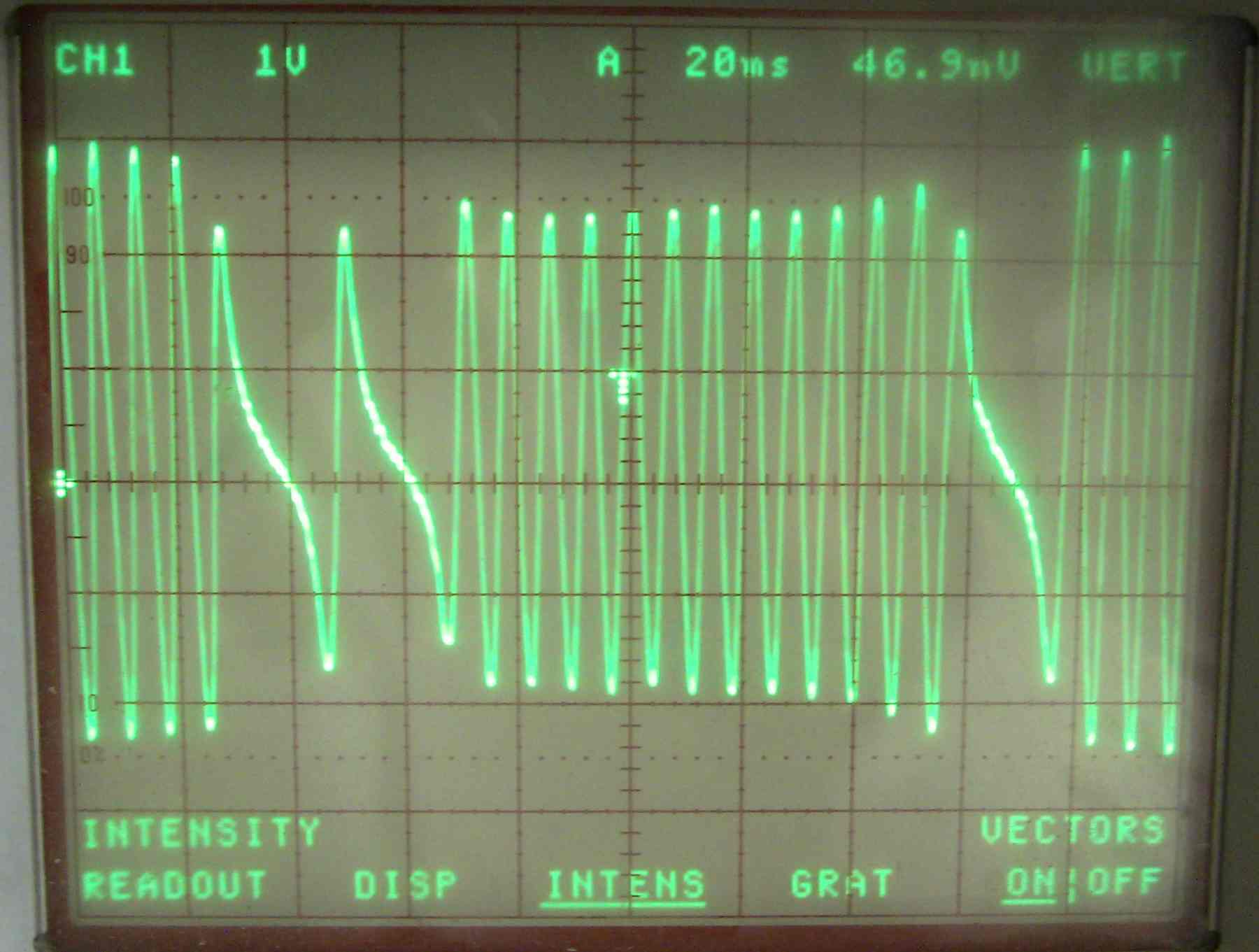
I suspect Tracy's PIC has its hands full at high RPM
reading this :) The single pulse by it self is probably
rotor one. The wide pulse is probably rotor 2.
I have no idea what Tracy is doing. He probably
considers the single pulse is the same as the
old 2nd gen crank angle sensor.
The easy way is to use 2 or more sensors, one for
each rotor, with only one tit on the wheel.
The pictures say it all. The router motor and
Harbor Fright (:)) motor control is the hot tip.
This thing runs smooth to ungodly RPM's (up to
22,000) thanks to Jim Poole's accurate machining.
If you want a RX8 trigger wheel hub and you need to ask
the price you can't afford it :) I have a spare one.
It is putting out a very strong signal with .2 inch
between the sensor and the wheel. On the order of
8 volts peak to peak. That is a stock, high buck, RX8 sensor.
Ill try it soon with the cheap $16 ABS sensor.
Be careful. Don't let it come apart. It can kill.
Paul Lamar
Paul,
That's great progress. I would be interested to see what effect a
non-concentric timing wheel would have. I found that mine had a
.0012-.0013" variation in the gap. I decided to go ahead and switch over
to
the Renesis water pump which will use the Renesis trigger wheel and hub.
This should cure the problem with changing gap, and possibly cure the
miss
too. It sure won't hurt anything. ;-)
Mark S.
That out of round is not going to help. It will vary the amplitude
of the signal once per rev. Jim Mederer tells me that is a common
problem with the e-shaft on the 3 rotor.
Good idea to go back to the 2nd gen CAS. Does Tracy have a different
software package for that or will it work with either?
I have no idea what Tracy is doing but reading the RX8 trigger wheel
and firing a three rotor is not an easy thing to do in software.
How are you coming with the Hytech ?
Paul Lamar
Paul,
We had our two grandsons for the weekend, so I haven't had time to mess
with
it. It was all I could do to keep them from burning down the house. I
did
manage to slip away and go to the airport on Sunday for a few hours (as
described above).
Anyway, I'm a bit confused on the Hytech's purpose. I know it is a data
logger, but you have connected some sensors. Is this to do compression
checks, or verify manifold vacuum, or both? I didn't want to exceed the
limits of the sensors by hitting them with 100 psi if they are meant for
vacuum.
Also, with the water pump off, I won't be testing anything for a while.
Mark
Those are for manifold vacuum and a crank angle sensor fed into
one of the A to D.
Your right. The sensors would blow up. These are the same sensors
Tracy's use in the EC2.
What you will get is a lot of raw data that looks like this.
BTW I don't think the 15 thou run out on the end of the
e-shaft is the cause of the miss. At what RPM is it missing?
I think you should borrow my RX8 trigger wheel hub and test
the EC2 with out the engine running. I think it has a software
problem over about 6500 RPM. You won't need the water pump
for that as they engine will not be running. If the injector
pulse width is not getting wider that is the problem.
In fact come to think about it I suspect Tracy's system
quits working after the torque peak as it is based solely
on manifold press and max HP comes well after peak torque
AND peak man press. If it has trouble sensing RPM
over 6000 it will not feed the additional fuel needed into
the engine at the same man press at the higher RPMs. Particularly
since you moved the torque peak down.
A car EFI systems uses a mass air flow sensor so
air flow is proportional to RPM as WELL as throttle
opening.
That explains a lot.
We need to hook up the Hytek and see what is going
on in Tracy's system over 6000 RPM with out the engine
running.
It is like trying to determine what some one is thinking
solely by observing their actions :) The hood is welded
shut :)
I have an early EC2 from the days when nobody went over
6000 RPM. Tracy has changed the software from that time.
We tried it on the p-port eng on the dyno but could not get
it tuned. We gave up at $650 a day and put the Weber on.
Perhaps we were having the same problem.
It might be interesting for me to hook it
up with the CAS simulator and see what it does
with my scope.
The bottom line is what does yours do?
Paul Lamar
Paul,
I agree, it would be very helpful to do a bench test on my EC-2. Bobby
Hughes has a scope we can use and I'm pretty sure I can rig it up using my
trigger wheel and my router/speed controller. Bob Darrah could fab an
adapter to fit my router.
There are two reasons I think this may be related. First, I can get
different results by changing the gap between the timing wheel and CAS
pickup. Second, Tracy recently commented that he had a misfire caused by
vibration of his CAS trigger bracket. He built a stiffer bracket and the
miss was gone. As I see it, a wobbling trigger wheel would cause the same
symptoms.
So, I think I will finish installing the Renesis water pump with new crank
hub and see if there is any improvement in how it runs. I can then do the
bench test if it still runs poorly. Keep in mind that before changing
engines this ignition setup would give me 7200-7300 rpm during the first
few seconds of my takeoff run. So, something has obviously changed, I
just
don't know what it was.
It may be that my exhaust system is too restrictive and is causing exhaust
gases into the intake charge at higher rpm. Lynn Hanover has stated that
the P-port engines don't tolerate exhaust restriction well. That makes
sense as a restrictive exhaust could force exhaust gases into the adjacent
intake during the overlap period. Come to think of it the rpm at which
the
engine began rough-running dropped after I installed the new muffler. I
may be on to something here... So, this may not even be ignition
related after all.
One question, what size air inlet should I have feeding the three 1-7/8"
ID
runners? Currently, I have a 3" SCAT hose with K&N filter.
Mark
I'll loan you my hub. No need for Bob to make one.
Well if you just go on area alone three runners are 8.28 square inches.
3 inch scat is 7 square inches. There is also skin friction drag pressure
loss in the tube due to velocity squared so I would go up a size or two.
There is 3.25 OD and 3.5 OD SCAT and SCEET.
SCAT is rough inside. SCEET is smoother but the inner liner
has been known to come adrift and plug it up. If you switch to
SCEET sew the inner liner to the outer liner with small diameter
safety wire.
Thin wall aluminum tube is best but I think about 3.5 inches OD would be
needed. You might want to roll your own out of .025" thick aluminum.
Send me some pictures of the P-port version of the 3 rotor.
Paul Lamar
Paul,
I've enclosed two pictures that show how it all came together.
You've confirmed that I need to enlarge the size of the intake tube.
Maybe
I can get some mandrel bent aluminum tubing and weld the pieces together
so
that I only have two small pieces of flex hose.
Mark
Nice tangential muffler.
Can you get a Harbor Freight inspection camera up the exhaust
pipe far enough to see the small holes in the center pipe?
Some could be failing.
Also nice job on the K&W duct on the oil cooler.
Can I see a picture of the other side of the engine? :)
Burns Stainless has some .065 wall 3.5 inch OD aluminum
90 degree bends for $105. Too expensive and too
heavy.
Carve it out of Styrofoam, wrap with vinyl electricians
tape and make a layup. The foam can be dissolved with acetone
and the tape fished out.
Paul Lamar
Paul,
Yes, I have a Harbor Freight LCD inspection camera and use it regularly.
I
can work it up the exhaust to where I can see a few inches into the
muffler. So far, everything appears to be in tact internally.
Mark
The muffler looks pretty good from the outside. How many holes
in that center tube and what is the diameter of the holes?
In other words what is the total area of the holes?
Somebody, I forget who, said that tangential mufflers can build
a complex internal pressure field due to the internal vortex.
The center of the vortex is low pressure while the outside
of the vortex is higher pressure. If this is true the center
of the field will be cooler as well. You might be able
to verify this with one of those non contacting infrared hand held
temperature gauges. The outer part of the vortex would then
apply more back pressure on the engine. That is the theory anyway.
Therefore you might try a separate 2 inch down pipe from the outside
of the can leading out, down and back. Make it temporary so it can
be removed and plugged up if it does not help. Leave this for
later after you have analyzed the electrical situation with the Hytech.
Robin is out of town on biz but I may be able to come down for a day
or two next week. Remind me to bring my infrared temp gage.
Paul Lamar
Paul,
That is a generous offer, but I work days (M-F) and our daughter is coming
to town Wed through Monday (6/16 - 6/21). I'm not sure what all they
have planned, but I really want to spend some time with her. She lives in
Denver, so I don't get to see her very often.
I need to order parts in order to get the opto-isolator board wired up and
ready to go. You mentioned a Panasonic part, do you have the p/n?
The tube running through the tangential muffler has 109 slits made with a
carborundum cutting disc (too &^%*$# difficult to drill holes in
inconel). The holes were then spread apart with a punch to form a bunch of
diamond-shaped holes. So, I would guess that the holes are 1" long and
3/8"
at the widest. I realized too late that it would have been better to angle
the slits to "encourage" the gasses into the inner pipe. I figured I
would compensate for that by using lots of holes (slits). I had thought
about adding an extra exit, or two. Or, I could open it up and replace the
2.5" inner pipe with a larger pipe. Or, I could remove the inner pipe
altogether.
Mark
I sent the jpg with the pin number on it.
Did you not get it? Here it is again.
It is a Digi Key CNS 7s something. 77 cents each.
Your muffler could be acting like an air compressor
with the hot air swirling around what amounts to a bunch
of cowl flaps. Air could be flowing into the exhaust pipe :)
Just add another exit and see if it helps.
Paul Lamar
Paul,
OK, the opto's are on their way.
Mark
At 250 RPM and .05 inch the signal is 5 volts peak to peak.
If the engine starts it must be close enough.
The scope picture is one half of a revolution.
Paul Lamar
The Rotary Engine NewsLetter. Powered by Linux.
ACRE NL web site.
http://www.rotaryeng.net
Youtube key word PaulLamar2
Copyright 1998-2010 All world wide rights reserved.