One of the drawbacks to mass air flow sensors
is the voltage is more or less proportional
to the cube of the mass air flow while engines
need fuel directly proportional to the mass air
flow. This is handled in most modern EFI's by the look
up table.
As far as I can tell the ZBasic function Exp()
can get the cube root so in theory no look
up table is required. It is similar to a manifold
pressure based EFI system were manifold pressure
is more or less proportional to the mass air
flow. Unfortunately therein lie the problems
we see in tuning as manifold pressure can be
affected by a lot of things.
Here is the ZBasicexp() function.
Type Function returning Single
Invocation Exp(arg)
Parameter Method Type Description
arg ByVal Single The power of e to be computed.
This function returns the Single value corresponding
to the value e raised to the specified power. The
transcendental value e, upon which the natural
logarithm is based, is approximately 2.718.
This function is the inverse of the Log() function.
A "Single" data type is in the range of
approximately ±1.4e-45 to ±3.4e+38 and 0.0
In QB the form is (xxxx)^.5 is the square root
of xxxx.
(xxxx)^.333 is the cube root of xxxx.
.5 and .3333 are the exponents.
So the exponent can be selected to linearize
the mass air flow sensor voltage out put.
I'll try this in ZBasic shortly,
I intend to use MAF as the basic means of
determining the correct fuel flow adjusted
by EGT based auto tune.
This is going to make tuning simple if not entirely
automatic if it works.
Paul Lamar
This is a clever approach. I believe you need a differential pressure
sensor with a static reference in the same environment as the pressure
probe. If an absolute pressure sensor is used, you will be taking the
cube root of (MAP + ram pressure). MAP is normally very much larger
than ram pressure. Using a differential sensor (i. e. MPX 2050) would
allow you to subtract MAP before taking the root.
Victor Roberts
Thanks Victor. We don't have a choice as the absolute pressure sensors
are built into Tracy's computer box.
BTW all standard aircraft
air speed indicators and air data systems work this way. Static pressure
is on one side of a diaphragm and dynamic pressure on the other.
The movement of the diaphragm turns the needle that indicates
air speed. Dynamic pressure is the square of forward speed.
Also there is an error in my message above. Can anyone find it?
Paul Lamar
cube
Cary
And?
Paul Lamar
Paul, about "and?" Actually it is not the cube of the voltage it is to the
fourth power of the voltage plus an adder. Using the table posted yesterday
I suggest the following. Add .85 to the voltage and take that to the fourth
power to get CFM. Note the ,85 constant is to provide a slightly larger Cfm
at higher airflows making a small leaning adjustment. The manual mixture
control or wide band O2 sensor will tune the output. If you divide the
above by 13.352 you have pounds of air per minute. Multiply that by 60 and
you have pounds of air per hour. divide that by 14.1 and you get pounds of
fuel per hour. Divide that by injector pounds per hour 39 in my case to get
percent of on time of the injector. That is then translated to pulse width
by the flywheel teeth count.
The math part of the above would look as follows
Using variable Va as the amplitude of the MAF output voltage
CFM= (Va+.85)*(Va+.85)*(Va+.85)*(Va+.85)
Pounds per minute =CFM/13.352
Pounds per hour = Pounds per minute X 60
Substituting I get ( ((Va+.85)*(Va+.85)*(Va+.85)*(Va+.85))/13.352)*60
Simplifying, Set Vb=Va+.85 and deviding 60 by 13,352 to get 4.4937
And define Pa =Pounds of air per hour
Pa=Vb^4*4.4937
Step 2, calculate pounds of fuel per hour Pf= Pa/14.7
Step 3. Calculate % injector open time for a 39 pound per hour ford
injector = Pf/39
For an example say the flywheel has 100 teeth on the ring gear, then pulse
width is the %open time above teeth count. If the flywheel has 137 teeth
multiply the tooth count by 137/100 for the tooth count .
The assorted constants for injector pounds per hour, baseline mixture and
flywheel teeth can be defined by their equivalent constant which I will call
Ce
ultimately Pulse width is (Va+.85)^4Ce which is the tooth count of
the flywheel
I view this as a conversion factor like changing inches to millimeters.
With one analog to digital conversion for the MAF sensor, A second one for
the potentiometer for manual leaning (using a similar conversion factor for
flywheel teeth) added to the above tooth count, and a counter for the ABS
sensor.
So what do you
think
george grimes
I am happy to know that somebody is actually reading this stuff :)
This is the error I made:
"voltage is more or less proportional to the cube of the mass air flow"
It should read:
"voltage is more or less proportional to the cube root of the mass air flow"
Therefor you have to cube the voltage out of the MAF sensor to
get the proper injector pulse width. Piece of cake in ZBasic.
Actually it could be anywhere between the cube root and the fourth
power. ZBasic does not care. What ever the mass airflow sensor
curve does that is the exponent you use. Say 3.5. It might not
be a perfect curve but it will be close enough.
In QB the syntax is "Pulse width times your constant = (Voltage)^ 3 to 4"
This is all opposed to a look up table which is a pain in
the butt to tune. EGT based auto tune will do the final adjustments.
The problem with counting the flywheel teeth for ignition purposes
with the ZBasic is it is not fast enough. That is why I am using an
external fly wheel teeth counter that updates the RPM count every .6 seconds.
That give the RPM in four digits to the nearest single revolution.
ZBasic could count each tooth if that was all it had to do.
Using the hardware interrupts in ZBasic to get around that
is problematic as all sorts of routines and instructions disable
the hardware interrupts. One of the critical ones is:
---------------------------------------------------------
PWM
Type Subroutine
Invocation PWM(channel, dutyCycle)
PWM(channel, dutyCycle, status)
Parameter Method Type Description
channel ByVal Byte The channel to use for PWM generation.
dutyCycle ByVal Single or integral The desired duty cycle.
status ByRef Boolean The variable to receive the status value.
This subroutine begins or modifies the generation of
a 16-bit PWM signal on the specified channel. The
channel must have been previously prepared for PWM
generation by calling OpenPWM(). PWM
generation is performed using one of the CPU’s
16-bit timers, the number of which varies depending on
the ZX model. The table below indicates the output
pin for each PWM supported channel.
The PWM free runs with a given width and frequency until the next
time it is changed. That frees the processor for other
jobs.
-------------------------------------------------------
Hard ware interrupts rapidly gets to be a real can of worms.
That is why I am doing the critical real time stuff like determining RPM
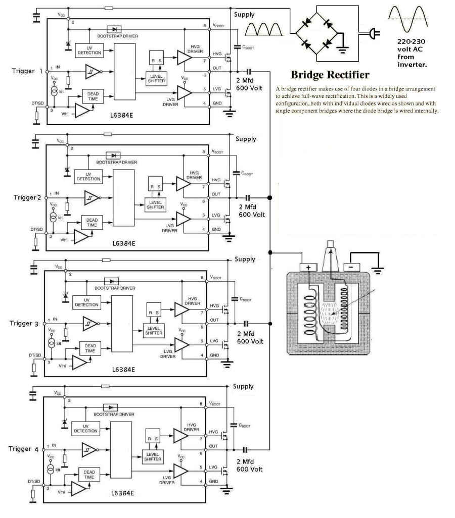
with the flywheel teeth and firing the ignition with simple external hardware
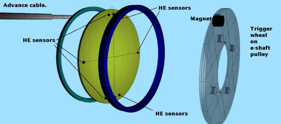
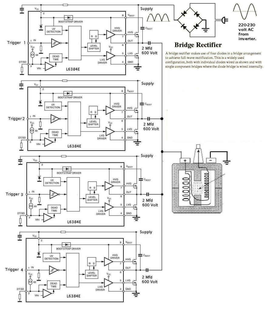
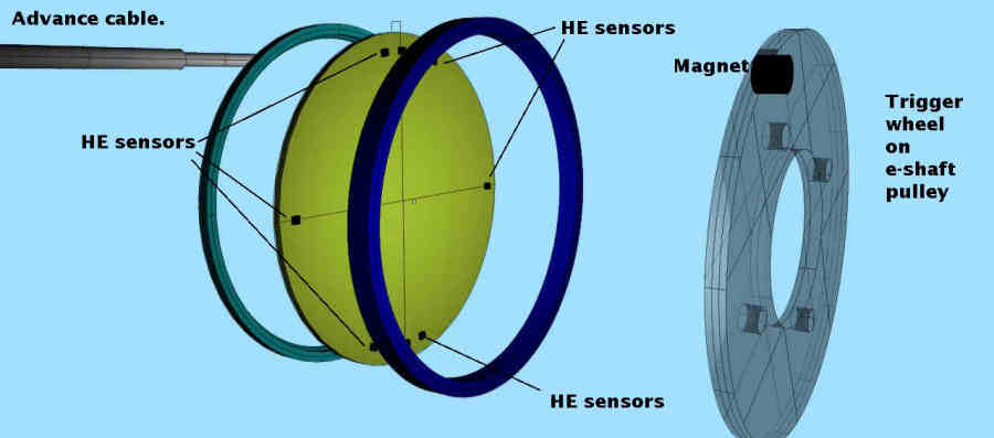
like two Hall Effect sensors for a two rotor and three for a 3 rotor.
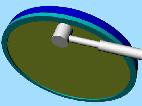
The ignition can be advanced with an old fashion push pull cable
like the Ford Model T. Easy to understand and fix.
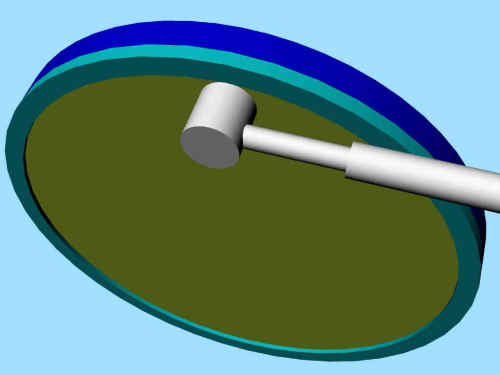
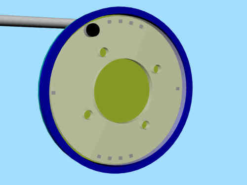
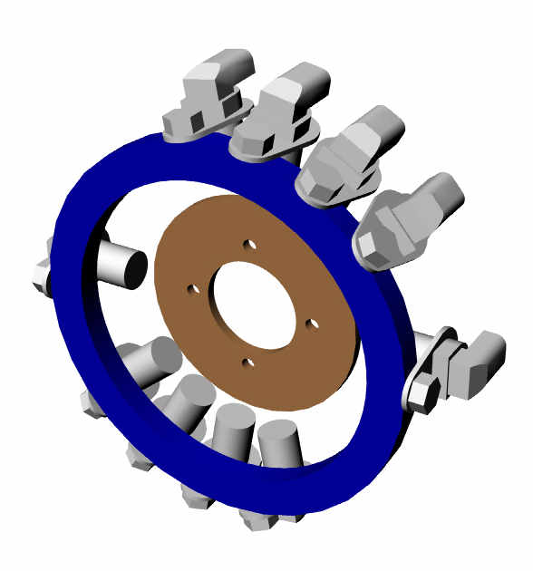
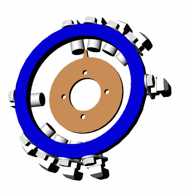
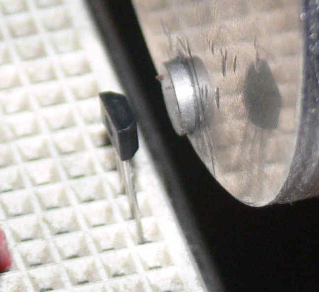
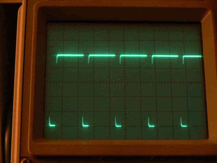
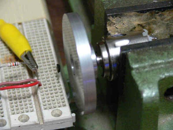
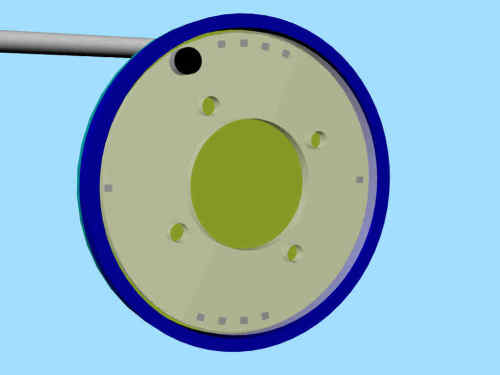
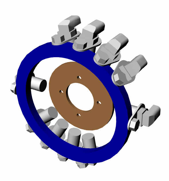
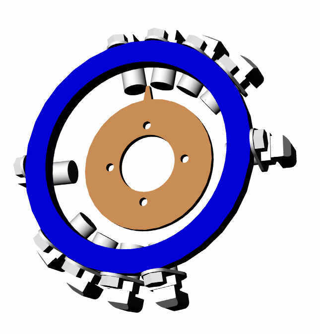
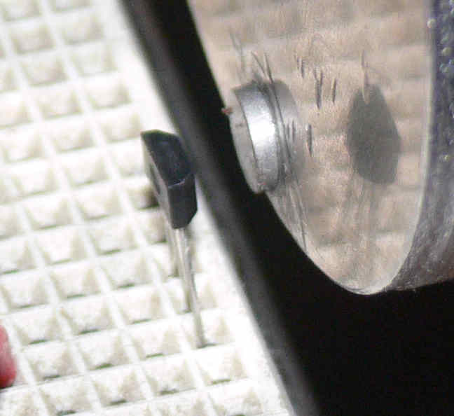
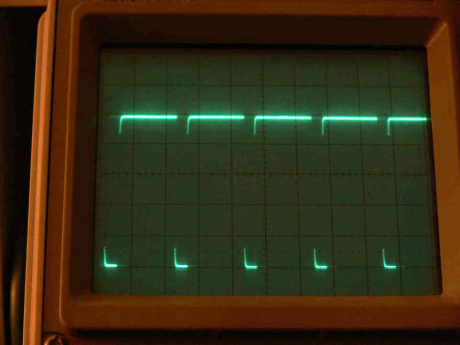
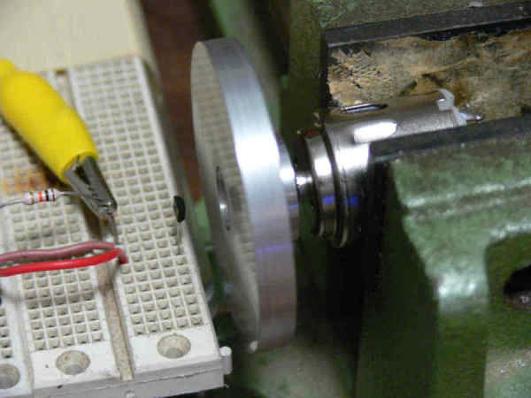
Here are some 3D's. I am going to use Hall effect sensors for the ignition
rather than the traditional mag crank angle sensor as they are much cheaper
and smaller. Therefor I can fire the ignition every ten degrees for 40 or 50
degrees to improve the fuel burn is it works. I have already done a skematic
and some R&D on that.
The RPM flywheel sensor will be the same as the stock CAS or
the ABS equivalent as hall effect sensors require rotating
magnets.
We are still in the planning stages here so a lot of suggestions
for improvement will arrive once people start thinking about it.
The $90 Atmel 1290 100 pin board is making it practical and it is
working to the point where ZBasic software changes are now trivial.
Tracy does this in assemble language software which is much faster but
it takes years to be good at it. I want to make this simple enough
so anybody can learn how to do it in a matter of weeks.
Paul Lamar
The Rotary Engine NewsLetter. Powered by Linux.
ACRE NL web site.
http://www.rotaryeng.net
Youtube key word PaulLamar2
Copyright 1998-2010 All world wide rights reserved.