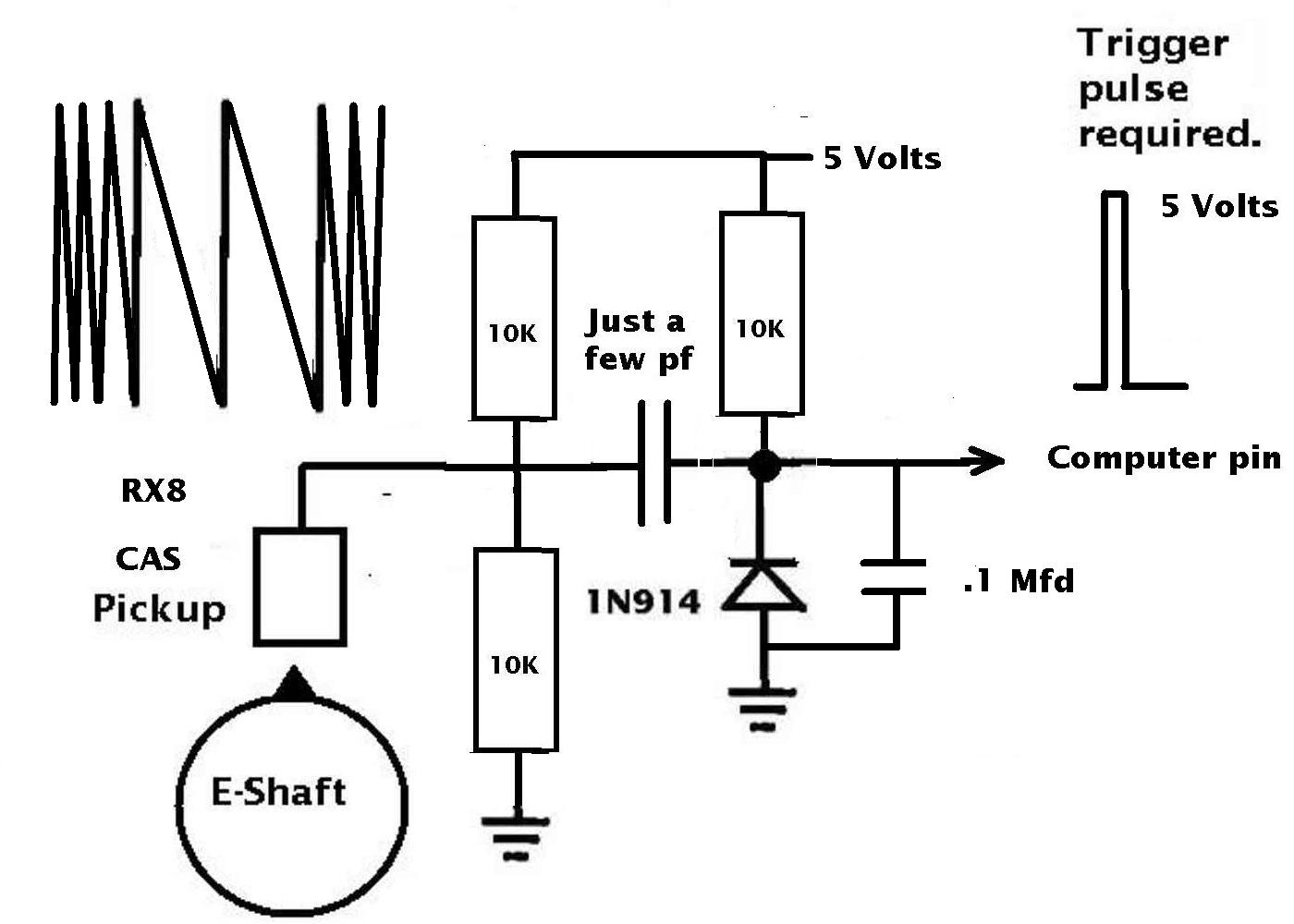
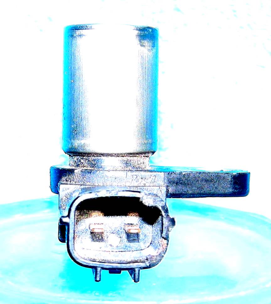
The RX8 trigger wheel is obviously
radically different than the old one pulse per rev
2nd gen CAS. (The CAS rotated at half e-shaft RPM)
Mazda probably changed the RX8 CPU processor
for a much more powerful processor than
the one used in the old 3rd gen.
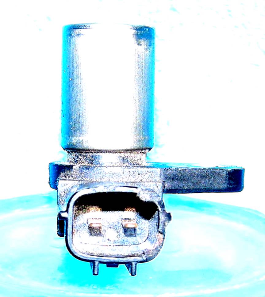
The 2nd gen CAS had two mag sensors. One
put out one pulse per rev and the other
sent a frequency that was proportional
to RPM to the processor. About 15 pulses
per rev or 2000 pulses per second
at 7500 RPM if my arithmetic is right.
Both the RX8 and the second gen have
about the same base frequency. Not only
can this be used for a crude RPM measurement
but as George recently pointed out it can
be used for deciding when to fire the ignition
for both rotor 1, 2 and 3.
The 2nd gen was the system that Tracy used to develop
his original system.
The RX8 must have been his worst nightmare
as Mazda combined these two devices in one
wheel and one mag pickup.
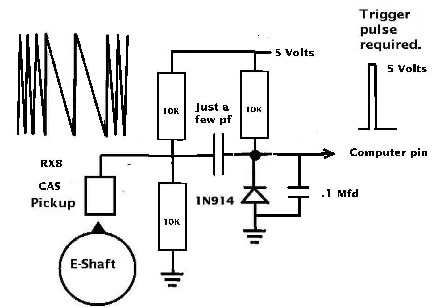
IMHO there are several ways of handling the unique RX8
pulse train. One hardware way is use a device
called a phase lock loop that syncs to all the
pulses coming in.
"Phase-locked loop is a feedback loop where a voltage-controlled
oscillator can be automatically synchronized "locked"to a
periodic input signal." Phase lock loops can sync to
a wide range of crude and variable input frequencies. They
are kind of in lock step with what is coming in.
Not only that they can multiply the frequency
so a more accurate determination of RPM can
be made. There have been some recent advances
in phase locked loops.
http://www.fairchildsemi.com/pf/MM/MM74HC4046.html
This device could be built into the new processor
that Mazda probably used for the RX8 or a discrete
chip added to the stock RX8 CPU mother board.
One software way is to interrupt the processor
2000 times a second and have it time how long
it takes to get to the next pulse. Not out of the question
for a modern high speed single chip computer programmed
in assemble language.I was doing that back in
the 1970's with a 6502.
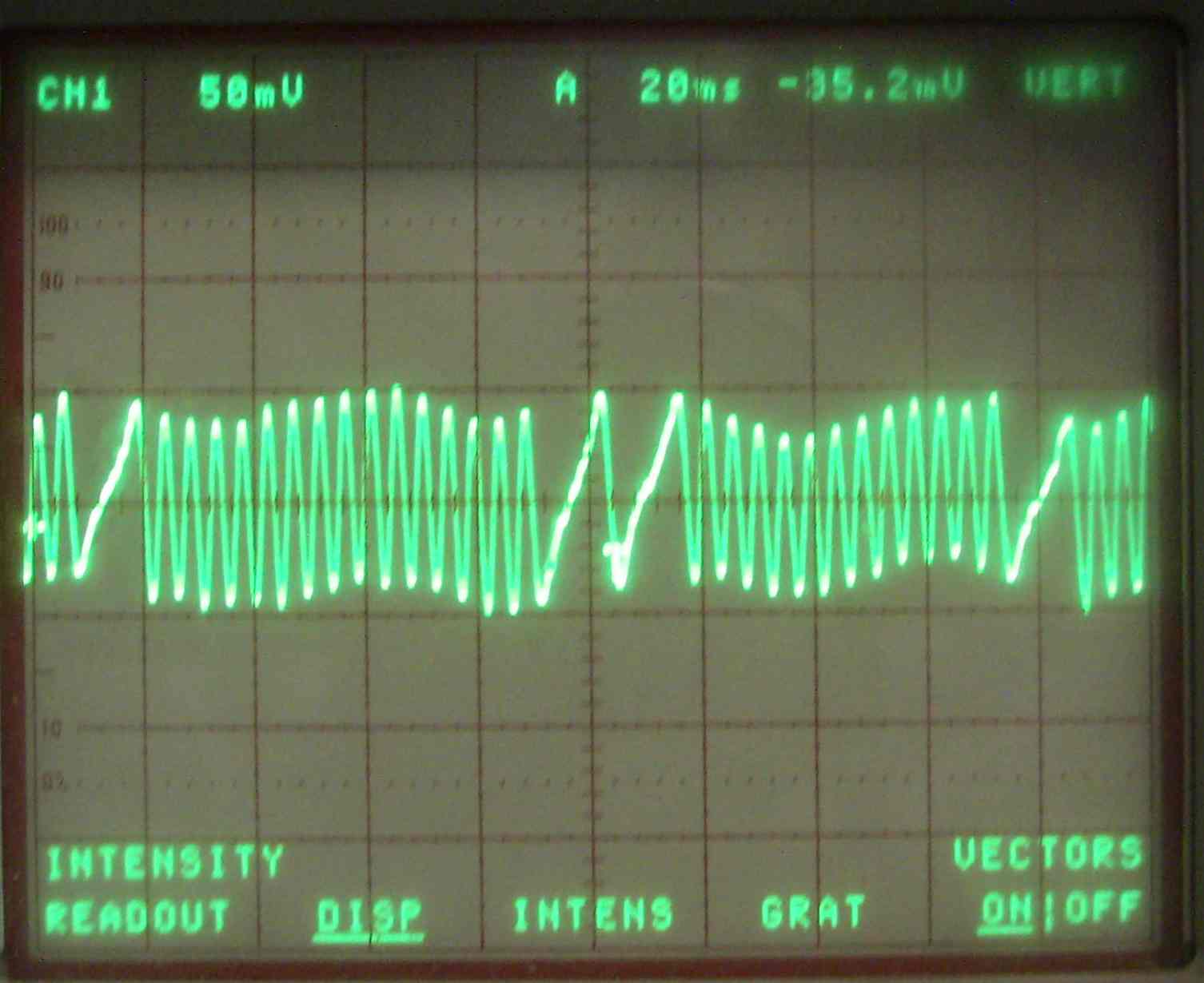
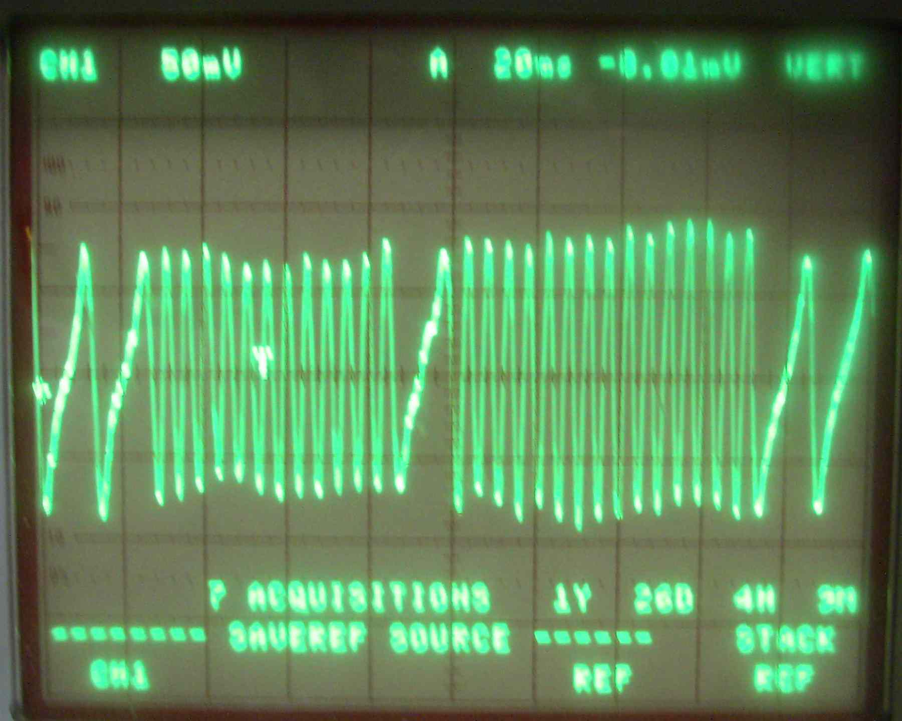
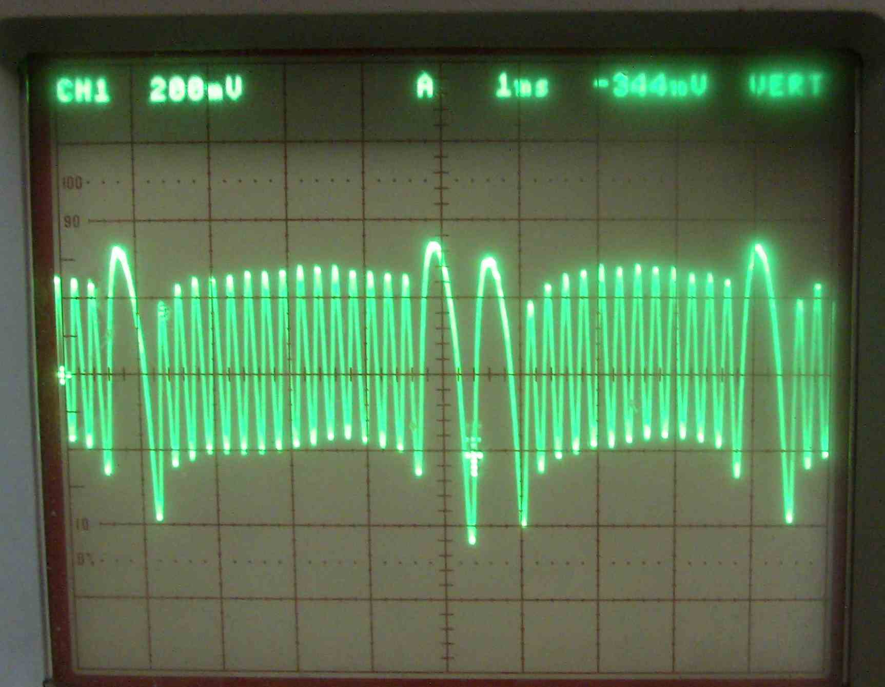
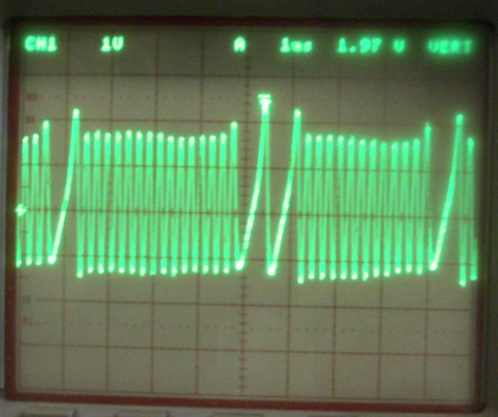
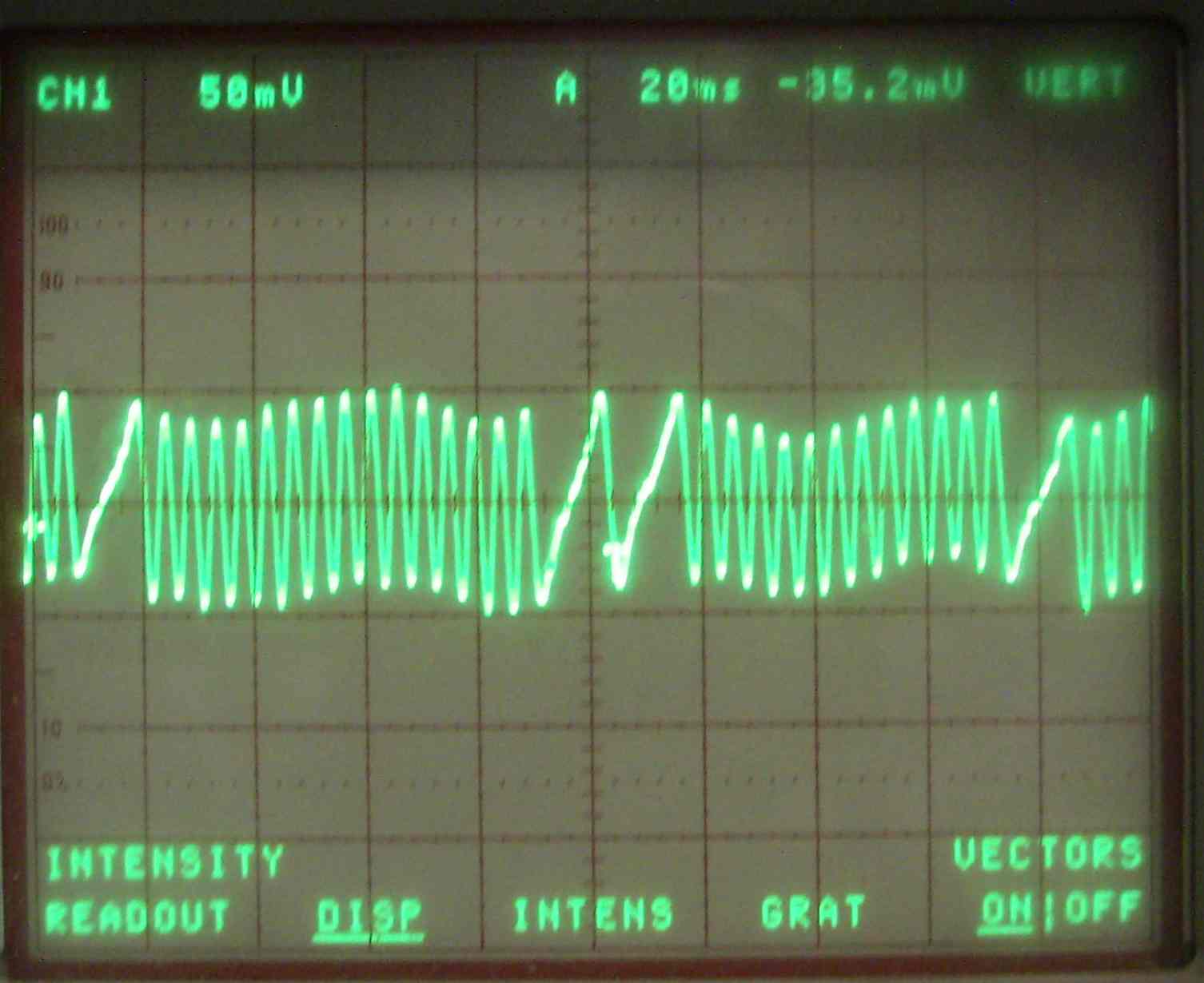
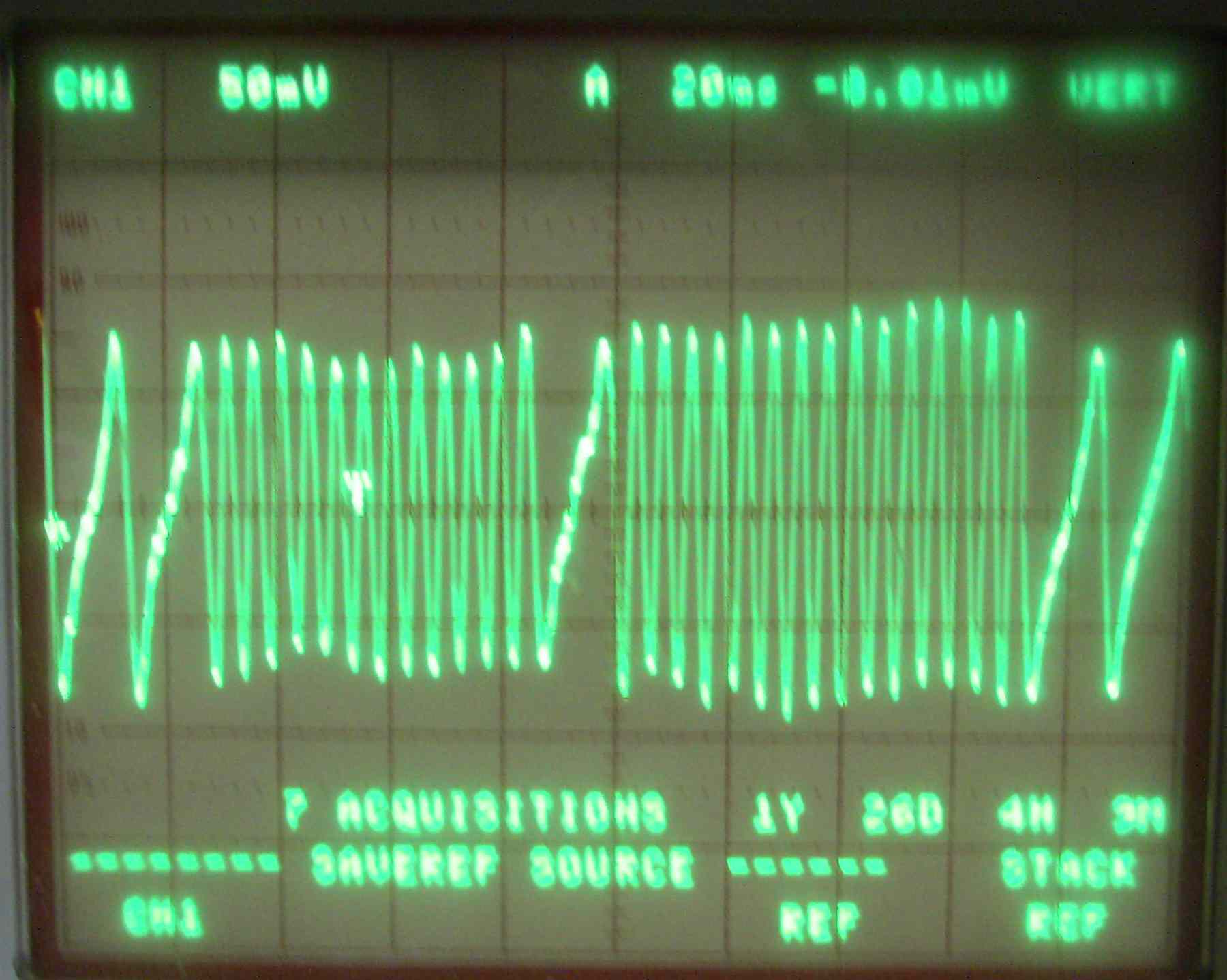
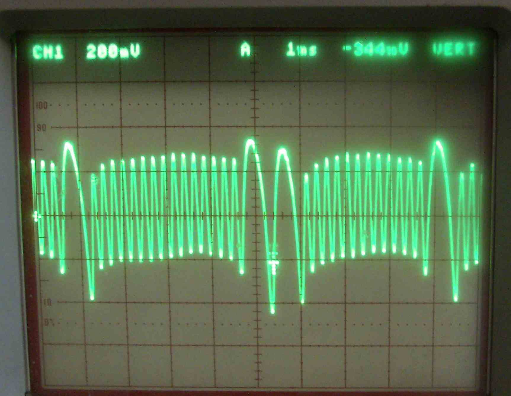
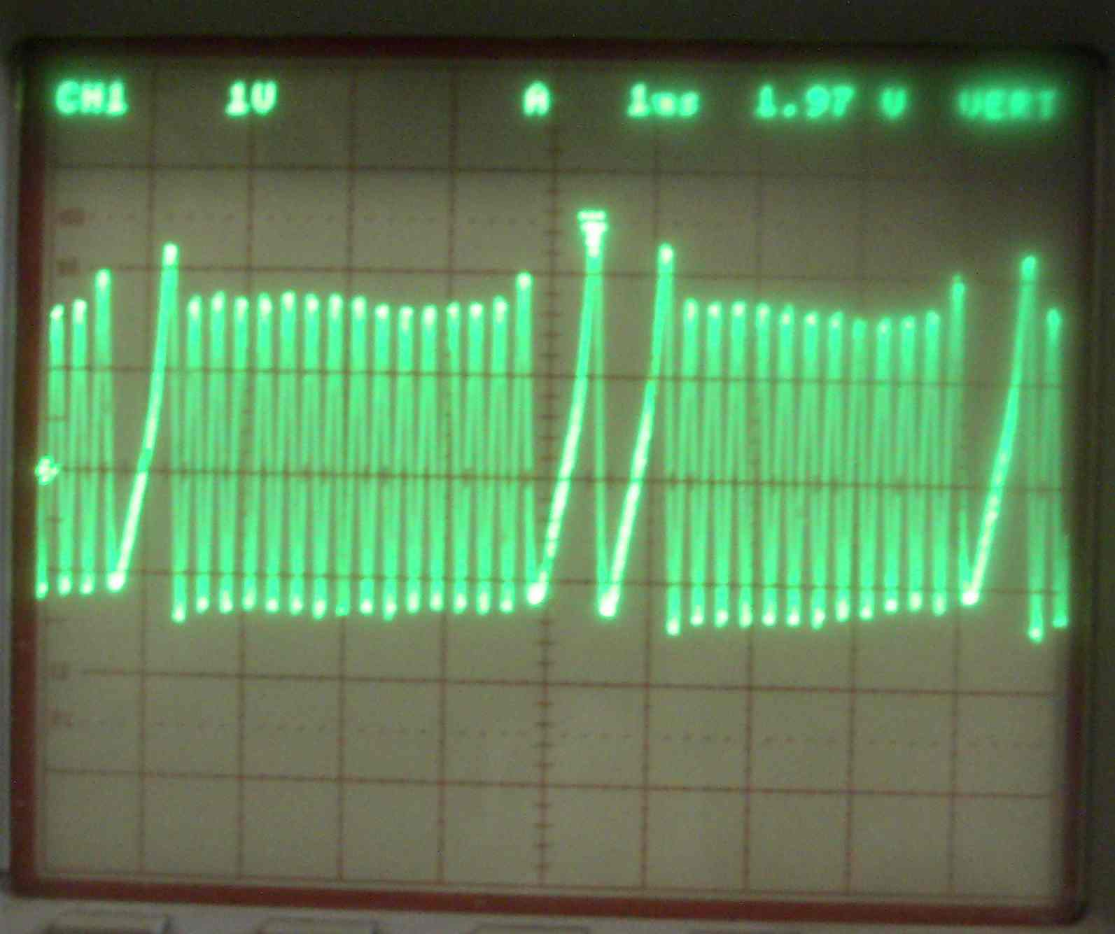
When I read the message below and checked it with
my used high buck storage O-scope at 7500 RPM
and 375 RPM with a 10X probe I was surprised.
For 7500 RPM and 10 volts per vertical division.
Note the reduction in max signal voltage from 30 volts
peak to peak with a normal 10K resistor to about 5 volts
peak to peak with the 1 K resistor. There is a significant
reduction in rise time as well. Fast rise times are desirable.
You can see high RPM tends to increase the signal level.
The story at 375 RPM cranking speeds is pretty much
the same. All four scope pictures are
attached. In the 375 RPM case the scope amp is set to
50 mv per vertical division which with a 10X
probe is really .5 volts. Peak to peak is less than
one volt. With the 10K resistor it is 1.5 to 2.0
volts.
With the 1 K resistor at 7500 RPM output
signal is only 5 volts with a slower
rise time. This could cause problems
at high RPM.
Computer chips have high input resistance so
most simple CAS type conditioning circuits only use
the top half or the bottom half of the AC wave.
IMHO I think it would be better to just shield the CAS
wire rather than use a 1K resistor.
Here are the O-scope pictures with and with out Tracy's
1K resistor at 7500 RPM and 375 RPM.
Paul Lamar
----------------------------------------
On 2/3/08, Tracy Crook <
tracy@rotaryaviation.com wrote:
snips...
BTW, all builders using the Renesis Crank sensors take note:
I had a lot of trouble starting my 20B with Renesis CAS
installed. Just yesterday I found out why. The Renesis CAS is
a much higher impedance sensor than the RX-7 CAS and this makes
it much more sensitive to noise pickup, especially when the
starter is running. It needs a load resistor across it to avoid
this problem. Install a 1000 ohm (1/4 or 1/2 watt is fine)
across the leads of the sensor either at the sensor or near the
EC2.
After installing one on mine it went from very difficult to instant
starting.
I'm not sure why I have not seen this problem on my RV-4 with Renesis
engine but one other Renesis user has seen the problem and the resistor
fixed it immediately.
snips...
A very small difference in how the CAS is
mounted affects the noise characteristics a lot. Either mount would probably
have worked fine with the resistor installed.
Future EC2s for Renesis engines will have this installed internally.
Tracy
--
The Rotary Engine NewsLetter. Powered by Linux.
ACRE NL web site.
http://www.rotaryeng.net
Youtube key word PaulLamar2
Copyright 1998-2010 All world wide rights reserved.