One of the most ubiquitous ignition systems on the planet.
Very popular with the Megasquirt crowd.
Old message:
"I'm investigating using two Ford EDIS ignition controllers.
They will work without computer input, set for 10 degrees
of advance. It just needs a power source and input from
a vr sensor. In normal operation, the computer sends
a correction signal that the controller uses to change
the spark advance. "
snips...
"The EDIS system requires a 36-1 wheel (36 teeth with 1 missing).
I'm thinking that one of the old bicycles that my boys never
use may end up missing a chain sprocket. (As a nod to the
original homebuilders, I think every homebuilt airplane
should include at least one bicycle part.)"
Enerst Christley
I think we can get along with one module and a
four cylinder two coil pack firing 4 plugs.
One coil can fire both leading and trailing
plugs using the four cylinder module.
Early version (DIS) are the most suitable as it uses
HE's to fire and is stand alone.
Does not need a computer.
Later ones (EDIS) use a mag pick and require a special
trigger wheel.
The six cylinder module can be used with a 3
rotor.
I am going to get one and test it.
---------------------------------------------------------
When you start to study the history of electronic
ignitions systems certain patterns and ideas
start to emerge. Ford patented the DIS system
back in 1990. The way the Ford EDIS system works for
a four cylinder or a two rotor is; a counter is preset
with the 1/2 the number teeth on the trigger wheel.
The computer goes away and does something else.
When the count is reached the computer is sent
a hardware interrupt telling it is time to fire
rotor 2 or the next set of cylinders.
This works over a wide RPM range.
The same scheme will work with a 3 rotor
or a 6 cylinder engine. The Ford used a missing
tooth detector so only one mag pickup was needed.
The 2nd gen Mazda RX7 CAS probably used the same
idea but there was no missing teeth and it
had two mag pickups. One gave a single
pulse at 20 degrees BTDC or so and the other
sent out a wave train of pulses that could be
counted. The mag pickups were/are called VR's.
That is why the 3 rotor could use the same CAS
as the 2 rotor. Just a different number was loaded
into the counter. Just about all single
chips computers have this type of hardware counter.
The drawback to these schemes is the timing is
not all that accurate. Especially the 2nd gen
as it does not have many teeth. The Ford
uses 36 teeth a number divisible by 2 or 3 giving
a whole number in both cases so it can be used with
a 4 or 6 cyl. engine.
I suspect Tracy is doing the same thing with
all of his systems.
Paul Lamar
Paul, why would the timing be inaccurate? Why would the number
of teeth matter, as long as the event happens at the same
place each time? Wouldn't the placement of the pickup set the
timing. What I mean is why would it change? I may just be
thinking about something different than you are when you say
accurate please let me know if I'm incorrect.
Bill Jepson
There is a certain amount of uncertainty when
the wave shape will cross the chip trigger threshold
level. These are not pure square waves. More like
a cross between a saw tooth wave and a sine wave.
You are more likely to get a more accurate count
to a higher resolution with more teeth.
We are talking microseconds here.
A system looking at fly wheel teeth would
be the most accurate assuming you know how
many teeth are actually on the flywheel.
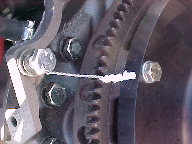
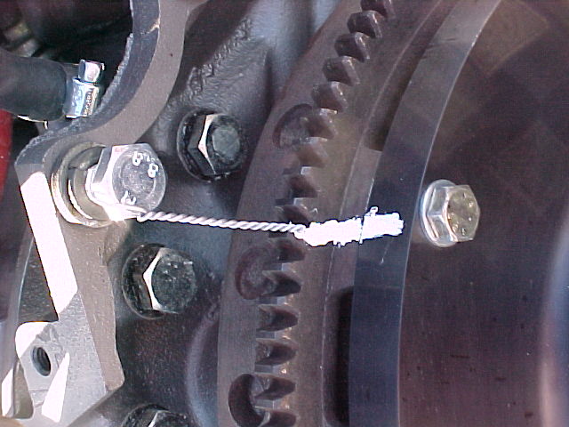
Here is a trick using the flywheel to accurately
determine TDC manually. See the attached pict.
BTW this will not work with the ZBasic
ATmel board because it depends on a rapid
and consistent time response to the
hardware counter interrupte.
One can simulate this is ZBasic software.
One can time how long it takes to count
to a given number three times in a row
in ZBasic using the micro timer and come up
with three different answers.
GetElapsedMicroTime
Type Function returning UnsignedLong
Invocation GetElapsedMicroTime(timeBuf)
That is because there are other interrupts
going on in the back ground such as the
real time clock update. These are unpredictable
when they will appear. You can wait for them
to appear and then do your timing but
that is a waste of processor time.
Check out the ZBasic Language Forum and find
my (Paul Lamar) subject "jitter".
That is why we are doing the time critical
stuff in hardware.
To do accurate real time programming the
programmer needs to know EXACTLY how long
any instruction will take to execute. That is why
Linux, Windows, C, BASIC and dynamic memory is useless
for true real time programming.
Only assembly language on a mother board, within the
limits of the directly addressable static memory
space will work. That's makes all Intel processors
after the 8085 useless for real time. As soon as they
put so called "memory management" (AKA bank switching) on
the chip it becomes useless for real time programming.
The old Motorola 68000 chip with a 32 bit address and
data bus could directly address any long word (32 bits)
within the 4 gig static memory space in a time predictable
and consistent fashion. That included the
memory mapped I/O of the 68K.
BTW the very first Apple MAC had the 68000
but not static memory.
Paul Lamar
--
The Rotary Engine NewsLetter. Powered by Linux.
ACRE NL web site.
http://www.rotaryeng.net
Youtube key word PaulLamar2
Copyright 1998-2010 All world wide rights reserved.