Paul,
Just playing around with some ideas on TC..This concept I am sending for
critique, understanding that this was put together in just a few
minutes...
The Idea here is to bolt the 2 exhaust housings up close and personal,
with some kind of adapter so they align with a sandwiched gear box that
resides where the compressor used to be, reducing rpm to the upper
shafts..
One shaft translates outbound to the single compressor in a housing
where it bumps the rpm back up to compressor speeds needed..the other
translate in the opposite direction that reduces rpm for the compound..
You can see built as oune complete body but don't have to tell you this
is all very modular with gear box housing and shaft housings as
separate..
All gear ratios and dimensions will adjust obliviously according to
design load and clearances..Certainly supported on the ends for rigidity
as well...
Jim talked about getting the turbo close to the exhaust port and also
keeping the compound shaft in perfect alignment outboard, this may be a
solution....
Be nice, I am very sensitive as you know...
jeff
No jpeg attached??????
jeff
Sorry Jeff. I think you are gearing it up and not
down.
Paul Lamar
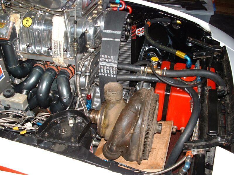
Jeff, Although I haven't done the CAD work on this I did research to find
out what type of system to use. There are manifolds allowing substitution of
one large turbocharger on a 13B which is thought to extract more power than
the two stock turbines which are limited in size due to the tight spacing.
Although you could connect two hot side turbines with an inconel coupling
that is a really harsh environment and temperature expansion has to be
considered. The major problem with turbo compounding is the 12 to 1 speed
reduction needed to connect back to the engine shaft. This is done with a
traction drive by rotrax or more commonly with multistage spurr gears by
procharger. To put these off the shelf items together the shaft of the
turbo supercharger would have to be replaced with one slightly longer and
providing a coupling for the procharger gearbox. Also needed is a bearing
housing fabricated to fit the compressor air horn inlet with the opposite
end adapted to the procharger gearbox. As with your model above the engine
drives the compressor at low speed and the exhaust turbine drives
everything at high speed. A waste gate is still needed in case the gearbox
becomes disconnected from the engine shaft.
I have seen an advertisement on the Internet for an assembled unit
incorporating these design features as a kit for isuzu engines which is
available only in Japan. The compounded supercharger is built by
rotrax and manufactured in Holland. I couldn't get any information from
rotrax or a price. There is apparently only one size and I don't know the
displacement of the isuzu engine it is used on or the amount of boost.
The shaft seems like a great excuse to use your CNC lathe. There are
steps, precision journals, tapers, and threads. It would also seem that
splines for a coupe ling might be necessary since it runs at 100K RPM.
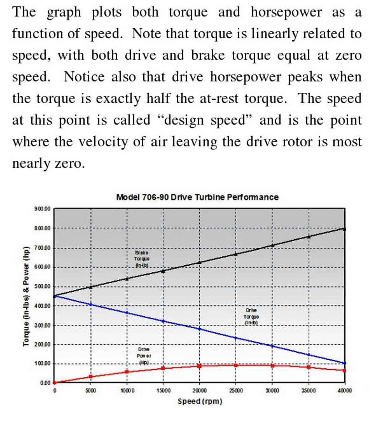
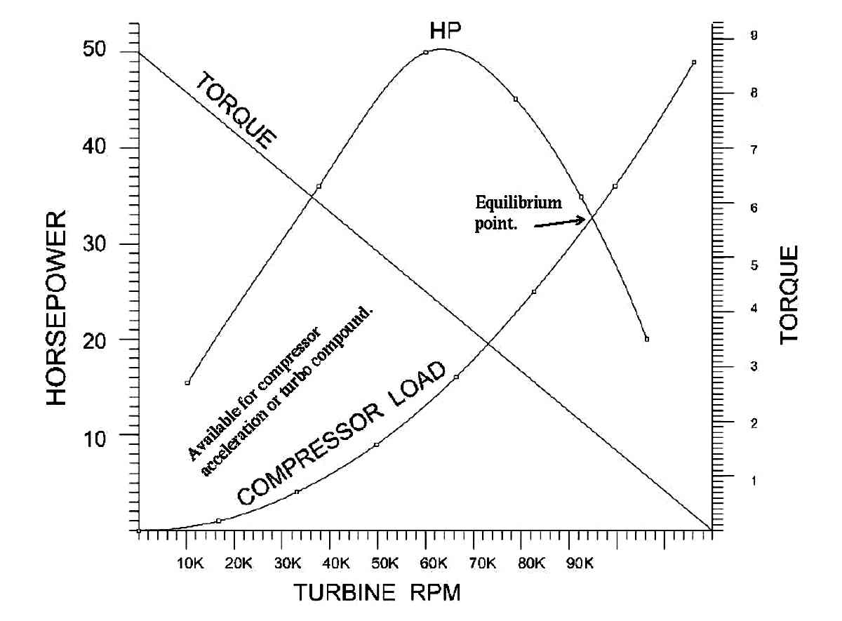
The torque of the high speed shaft should peak under 30 ft lbs at
start up and fall to 7 ft lbs at full speed. I like the one large
turbocharger because it can have a larger diameter shaft which would be
better to adapt a coupling to.
One question about your design above. Are you gearing down to the
drive shaft then gearing back up to get a different speed on the compressor
than the exhaust turbine rather than having them run 1 to 1 ?
george grimes
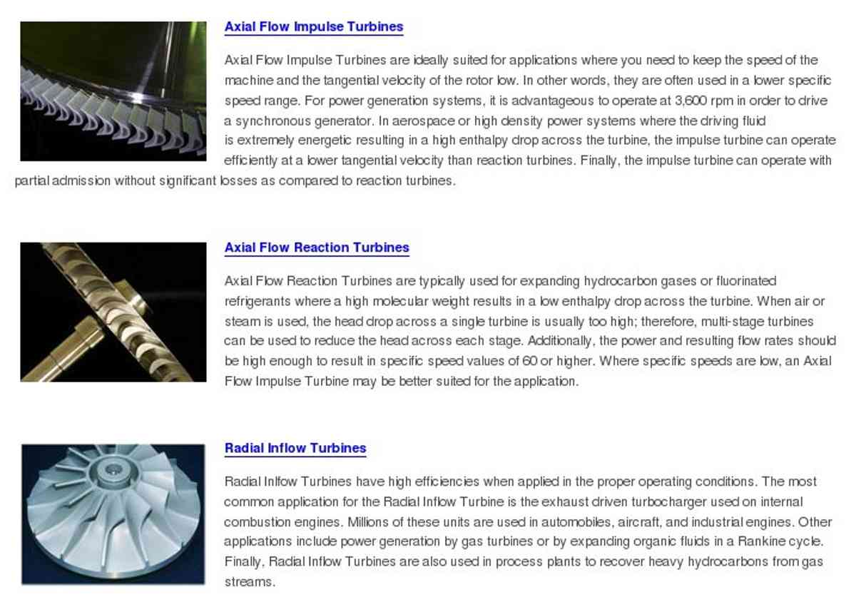
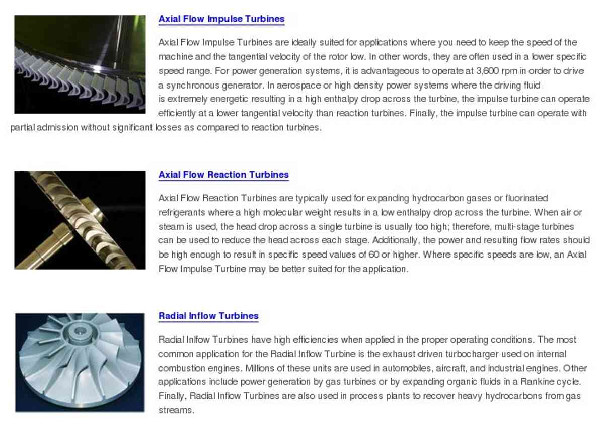
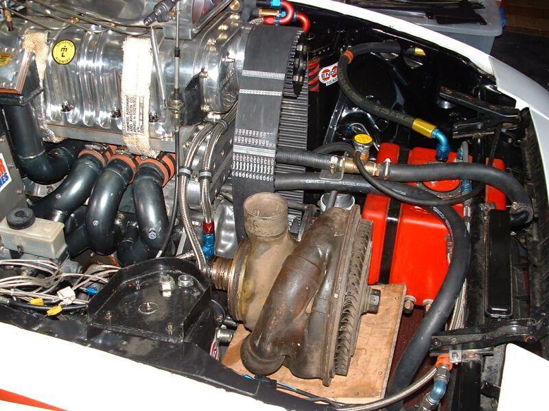
Doug Fir has a rotrex George.
Here is some info. I am using the same friction gear box in my design.
Paul Lamar
Paul,
My recollection is that turbine efficiency is somewhat tied to RPM
because the speed of the gas flow must be matched to the speed of the
turbine blade.. Why not go to a larger turbine which would allow a
lower RPM for a given blade speed? I realize a larger turbine might
be heavier overall, but if it were limited to a lower RPM, savings
might be possible.
RPM (Speed) is directly related to circumference, which has a linear
relationship to diameter.. Double the diameter of the exhaust, and
that should halve the RPM for a given blade speed. We'd want a very
large exhaust wheel with very tight flows compared to what's probably
already on the market.
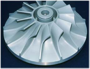
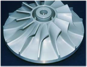
I wonder if it would be cheaper to have a custom turbine wheel made
for an existing large housing than to use a design that requires such
a large and high speed reduction ratio. It would certainly be
simpler.
I know we have talked about a direct drive to the e-shaft system in
the past, but I think an intermediate step that only required a 3:1
reduction might be worth considering.
Regards,
Matt-
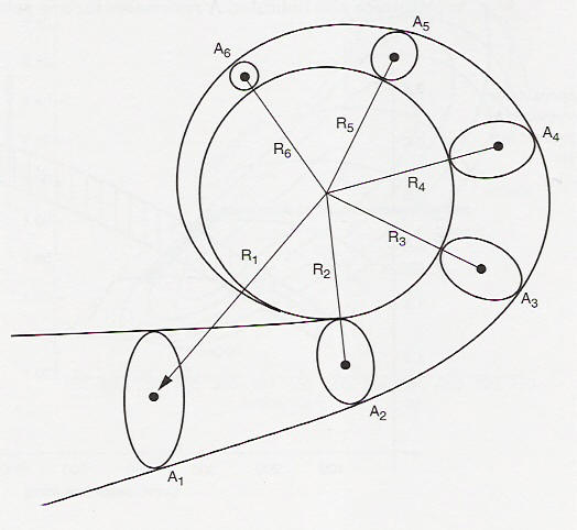
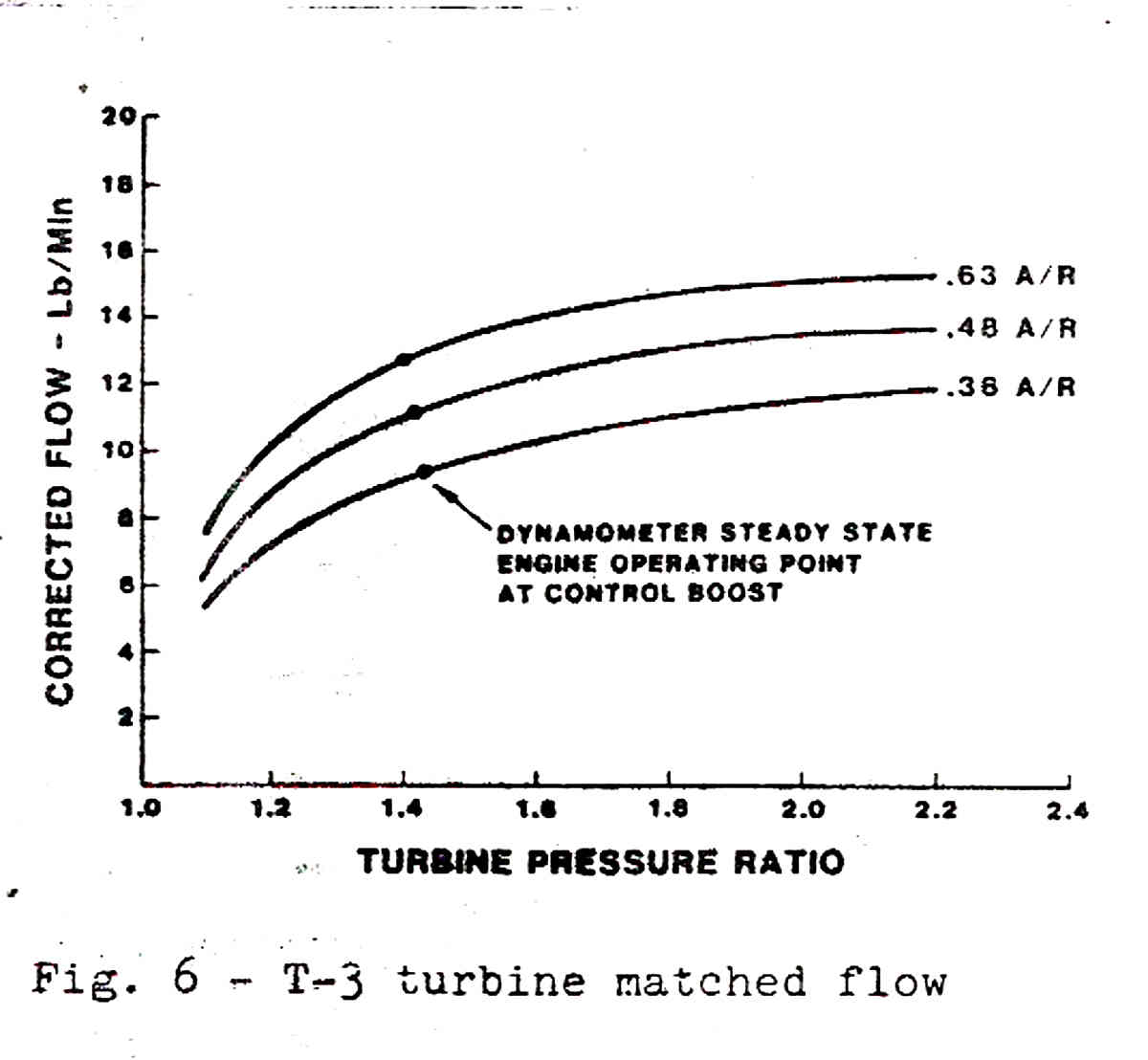
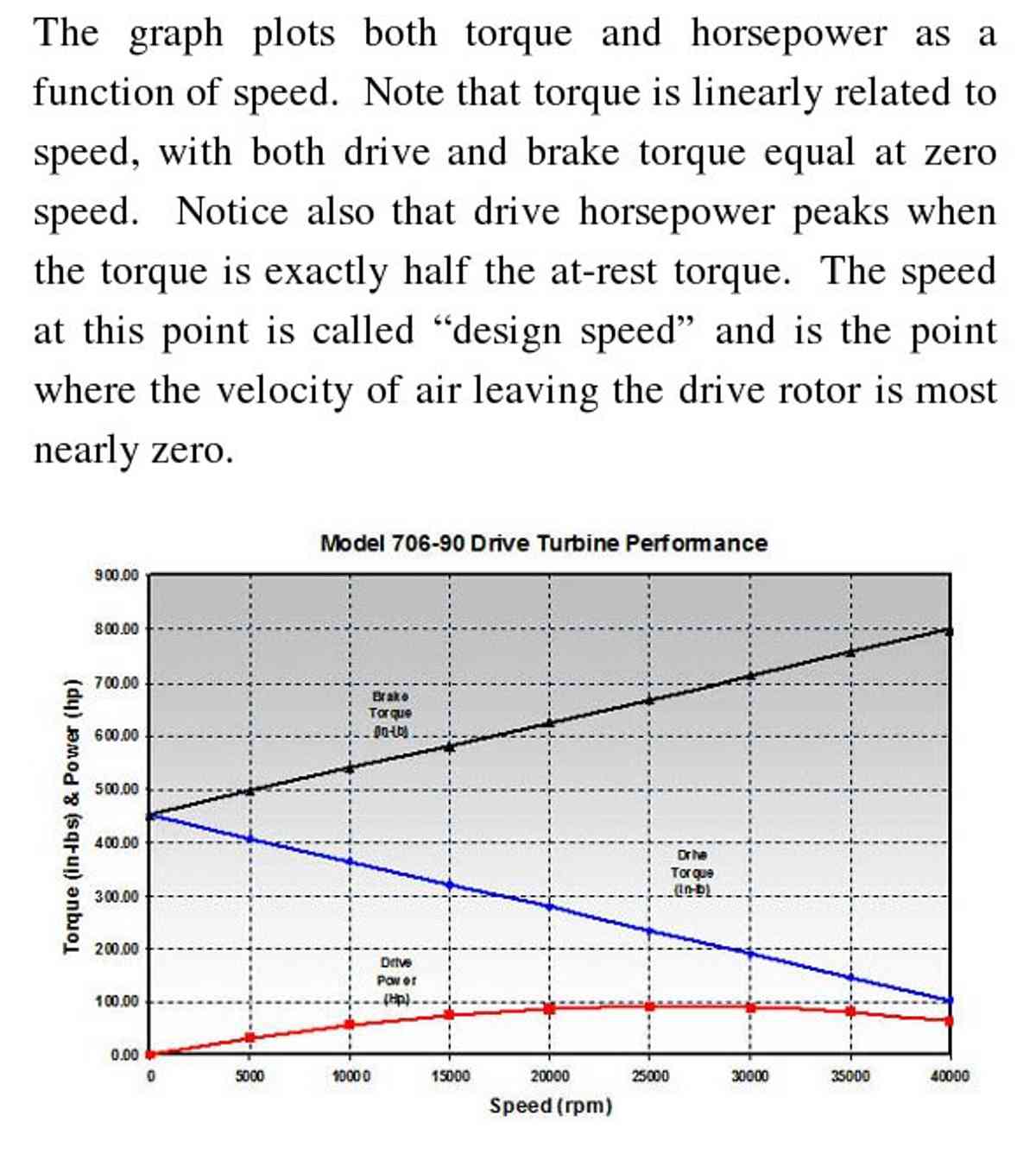
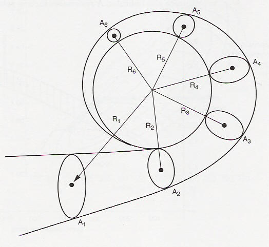
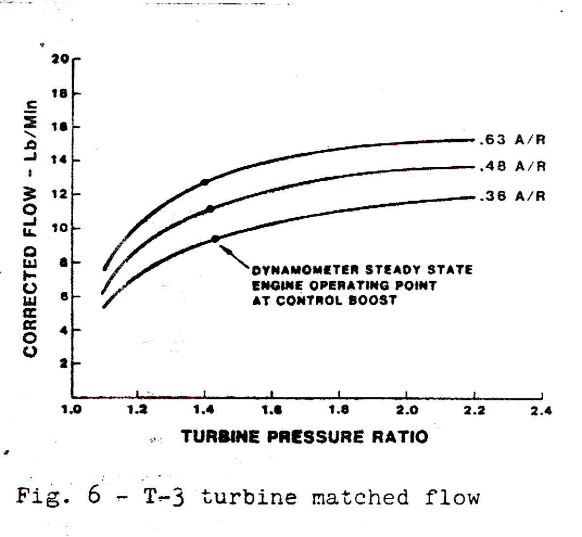
The key is blade velocity as a ratio of gas velocity out of the nozzle.
The A/R relates to the nozzle.
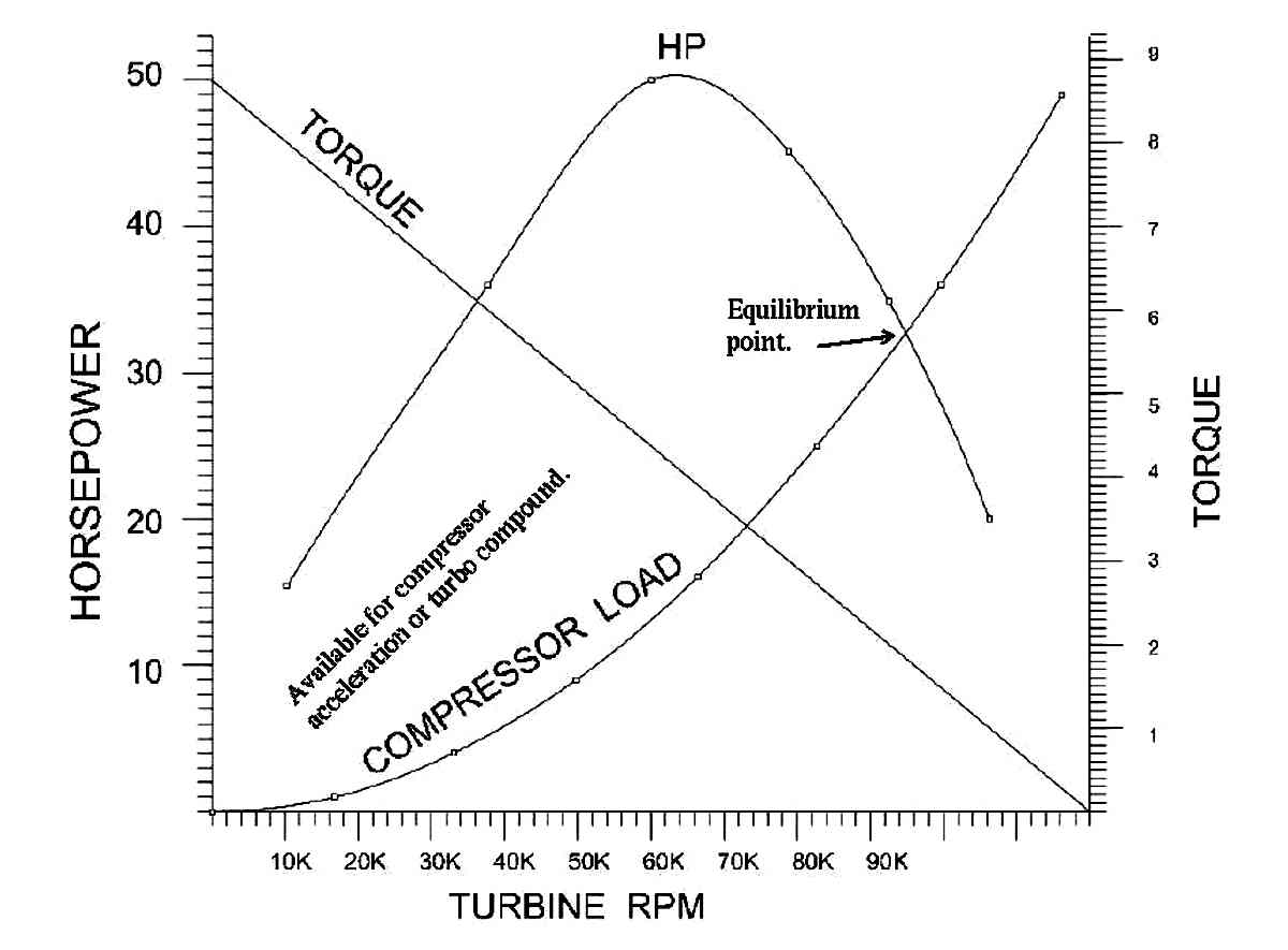
Torque is a maximum when the blade is stalled and zero when
blade velocity equals gas velocity.
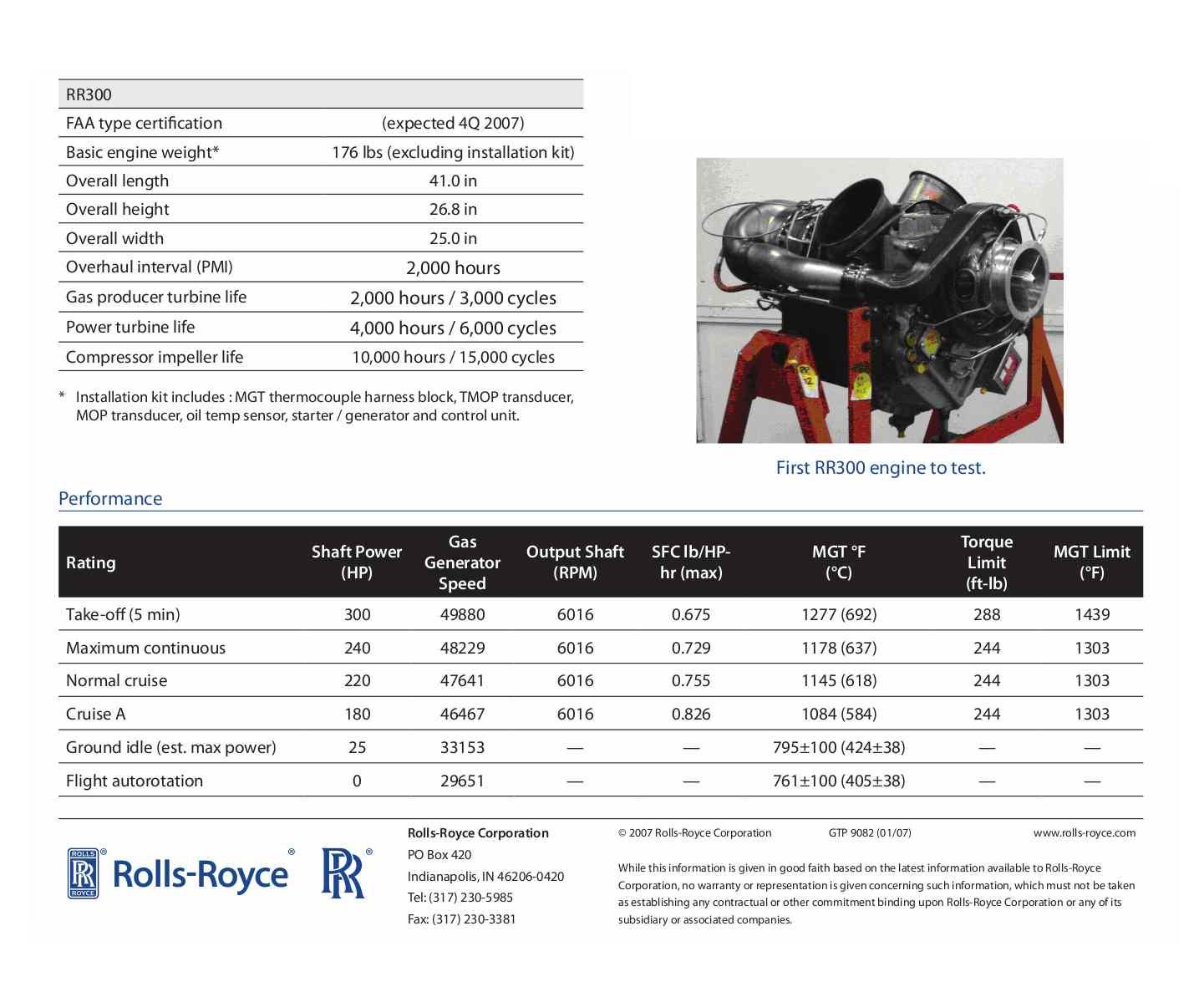
Here is the HP out.
Paul Lamar
--
The Rotary Engine NewsLetter. Powered by Linux.
ACRE NL web site.
http://www.rotaryeng.net
Youtube key word PaulLamar2
Copyright 1998-2010 All world wide rights reserved.