I was surprised at the size of the capacitors
so that added a bit of square inches to the
PC board. Back in the old days (60's) we used
large metal can capacitors that were oil filled
for our CD systems and vac tubes of course.
Those caps store the spark energy instead of
being stored in the coils. CD coils
run cool as they are simply used as pulse
transformers.
Boards cost about 65 cents per square inch
Plus a fixed cost of $55 for tooling.
The caps are the 4 big boxes in the center of the PC
Board. I'll use my favorite heat sink and
TV connector for the output to the coil.
This is for one spark plug on one rotor.
The trailing plug does not need it and
and any back up ignition can be used on the
trailing rotor.
This requires 4 Hall Effect devices
per plug to trigger every 10 degrees for
40 degrees after 22 degrees BTDC.
In other words 20 BTDC, 10 BTDC, TDC and
10 degrees after TDC with no RPM limit
such as MSD's have problems with.
One cap for each spark.
The whole idea here is to see if it will
cut the fuel burn.
I'll see if I can get Mazdatrix to test it on
the dyno. I'll loan it to them for use on
what ever engine they are fooling with at
the moment.
It uses one 400 watt 220 Volt AC off the shelf 12 V power
supply for up to 6 PC boards if you want to implement
that many on a 3 rotor.
Paul Lamar
It would appear that isolation devices are needed between the four 2mfd
caps
and the coil. When trigger is low, there is a low impedance to ground thru
the lower FET of the half-bridge, essentially putting the caps of the
untriggered drivers in parallel with the coil.
Victor Roberts,
Yes I see what you are saying. It is helpful I have other engineers looking
over my shoulder.
I need some more switches in there.
Thanks Victor. Do you have any suggested circuits?
Paul Lamar
The current configuration still leaves the 3 untriggered caps with one lead
open. This does not put them in parallel with the coil or am I missing
something?
Dick Handverger
Thanks Dick.
First condition. All caps are fully charged through the coil.
This group is in series with the coil. The problem Victor pointed out was
when any lower gate closed all caps now in parallel would be discharged
through that gate bypassing the coil as that would be the path of
least resistance. The coil would see no current flow.
I think I need Triac's in series with all caps to prevent that from
happening so only the coil sees the sudden increase in current.
Triacs are bidirectional switches unlike most semiconductors.
They look like a relay contacts. Relays contacts don't care
which way the current flows.
All Triacs need to be on when no trigger pulse is occurring so
the caps can charge through the coils. Only the Triac that
is associated with the trigger pulse stays on when the trigger
occurs.
I have yet to figure out the logic on how to do that
short of a computer. Any suggestions?
Here is an incremented schematic.
---------------------------------------------
Here is the truth table. Output refers to the triac.
0 is off and a 1 is on.
Looks like I will need a programmable logic chip
with 4 inputs and 4 outputs unless somebody can
come up with a better idea.
The all triggers on condition never happens.
In that case there is an error so all triacs
should be off.
Paul Lamar
It's 4 inputs.. Can handle that with combinatorial logic too.
Here's a neat tool:
http://www-ihs.theoinf.tu-ilmenau.de/~sane/projekte/karnaugh/embed_karnaugh.html
Clicking on each output square causes the Boolean expression to be
calculated..
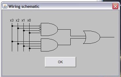
For each output, it came up with /x3&/x2&/x1&x0+x3&x2&x1&x0..
Attached is a pic of how it looked when I selected the expression..
Regards,
Matt-
You lost me Matt. Can you translate into to Dick and Jane?
How would I translate that into hardware.
Paul Lamar
Your message included a truth table for the drive of each coil. A
circuit could be made from combinatorial logic using AND, OR, and NOT
gate chips.
An efficient Boolean expression of a truth table can be made from a
Karnaugh Map. Gray code transitions of the inputs along the edges of
the Map, and the desired output states within the Map. In this case
the Map needs 16 states on the output because there are 4 inputs
(triggers).
Once you fill in the map with the desired output states you can draw
bubbles around binary groups of set bits. In this example there are
only just two set bits of sixteen. The expression will be the sum of
the products which describe each of those bits.
The tool I sent you automates the process. It also will draw a
minimized circuit with gate symbols. Click the button for English.
I have attached a pic of a circuit diagram that would accomplish this..
A circuit like that would provide the logic in discrete components
instead of using a programmable logic chip as you had mentioned.. You
would need 4 such circuits, each one with the inputs swapped around
slightly.
The circuits would be made up from CMOS logic chips. AND, OR, and NOT
(inverter) in this case. Each chip has a multitude of IO's and gates.
I'm not saying this is the best way, but it would be very cheap.
Matt-
That looks like an interesting tool Matt.
Paul Lamar
--
The Rotary Engine NewsLetter. Powered by Linux.
ACRE NL web site.
http://www.rotaryeng.net
Youtube key word PaulLamar2
Copyright 1998-2010 All world wide rights reserved.