Please look this over carefully and if you
see any mistakes please let me know.
Paul Lamar
Hello Paul, Tracy and Mark,
4000-series CMOS IC's are very vulnerable to static electricity.
I suggest that you must ensure that there are safeguards in place to
prevent the IC from getting "zapped" during load dumps or other electrical
system events.
It would be much preferable to use mil-spec components, such as a
54HCU04.
This is a high-speed unbuffered TTL-level CMOS hex inverter that can be
pressed into service as an open-loop amplifier.
The INPUTS to any unused inverters must be connected to either Vdd or
GND/Vss to prevent high-frequency oscillations/instability.
The schematic does not have any protection for the input to the gate. I
suggest 1k to 10k Ohms.
There are no clamping diodes. These are a must. 1N914/1N4148 diodes
would be sufficient; one from the Vdd rail to the input (cathode to Vdd)
and
one from the input to GND/Vss (anode to GND/Vss).
There is some overshoot on the 'scope display. This is due to the
inductance of the wiring not being damped with resistors in the signal
path.
Low-value resistors (say, 47 or 51 Ohms) at the input to the next stage
will
help a great deal to eliminate the overshoot.
Regards,
Steve in Orlando
I'll turn over all the PC board design work to you Steve if you want it.
Here is the latest schematic and board design.
Paul Lamar
---------------------------------------------------------------
Well, I'm afraid that I first need to poke some holes in the design
concept. Please try to not hate me for doing this, as it will save you money and
grief even in the short run.
Let's start off with your 555 timer circuit. I see "26.656 CPS" above the
timer.
That implies you expect a great deal more precision out of the timer than
you will actually receive.
Did you know that 555 timer circuits in an astable multivibrator
configuration are only accurate to within around 2% on a good day going downhill
with a tailwind?
That means your actual frequency out (if you managed to get it set
initially to a perfect 26.656Hz) will vary from around 26.389Hz to around 26.923Hz
(rounded off a bit). That's just the error in the 555 timer itself, and
doesn't take into account the variations you'll get from the timing cap
changing over temp.
Using a 500k pot to trim the thing (even a 21-turn pot) will be very
finicky, to say the least.
If you want a reasonably stable timebase, you really need to go to a
crystal oscillator. If you want a REALLY stable timebase, you need to use an
OCXO (oven controlled crystal oscillator). This is not as difficult or
expensive as it sounds. You can spend a hundred bucks on an OCXO, or you can
make one yourself for a buck or two.
See Roman Black's OCXO page:
_http://www.romanblack.com/xoven.htm_ (
http://www.romanblack.com/xoven.htm)
Let's cruise on over to the right side of the schematic where you have an
LM78LXX.
LM78Lxx regulators are rated for operation with a junction temperature of
0°C to 125°C in the TO-92 package, and -40°C to 85°C in the micro-SMD
package, neither of which meets the temperature range specifications for
automotive use, let alone aerospace use.
The maximum input voltage for the LM78L05 is 35v, which means if you have
a load dump spike, the 220uF cap will charge to around 60v and fry the
regulator to a crisp. Got a marshmallow on a stick?
Let's have a look-see at your 4520 /16 QD. You have an LED on the output
with a 4.7k current limiting resistor to ground, and then you have the 1nF
cap and another 10k resistor to ground. Call me persnickety if you must,
but I really don't like to see much more than a 10k load on 4000 series CMOS
outputs.
This could be achieved by using a ~15k resistor to the base of a Darlington
transistor (like an MPSA14) or N-ch enhanced MOSFET like a 2N7002 to sink
current from the LED, and then use an appropriate resistor to the 5v
supply, say 200 Ohms. Change the 10k resistor by teh NAND input to 47k-100k.
Your LED will now flash nice and bright, and there will be very little load
on the output of the the 4520.
Back to the input of the NAND gate 2; you need to clamp the input to ground
using a diode so that it cannot go below ground. As it is, the average
voltage on the input will be zero, but you will have excursions both above
and below ground; the latter of which is not good.
Similar with the CD4011 #1; it needs clamps so that the signal cannot
cause the input to drop lower than ground or higher than Vdd. There should
also be a resistor to limit current to the input and clamps.
The three hex counters on the bottom - did you know that the 4520 clocks on
the rising edge?
I think that you were expecting a nice count from x000 to xFFF, but what
you'll get is a count from 0 to 7, and then when QD goes high for the
8-count, the 2nd 4520 clocks. Is that what you expected?
I have a feeling you thought it was going to clock on the falling edge; I
don't know.
Meanwhile, I don't know why you are using up two 8-bit ports and board real
estate just to provide a three-byte counter.
I must be missing a bigger piece of the puzzle here.
Steve
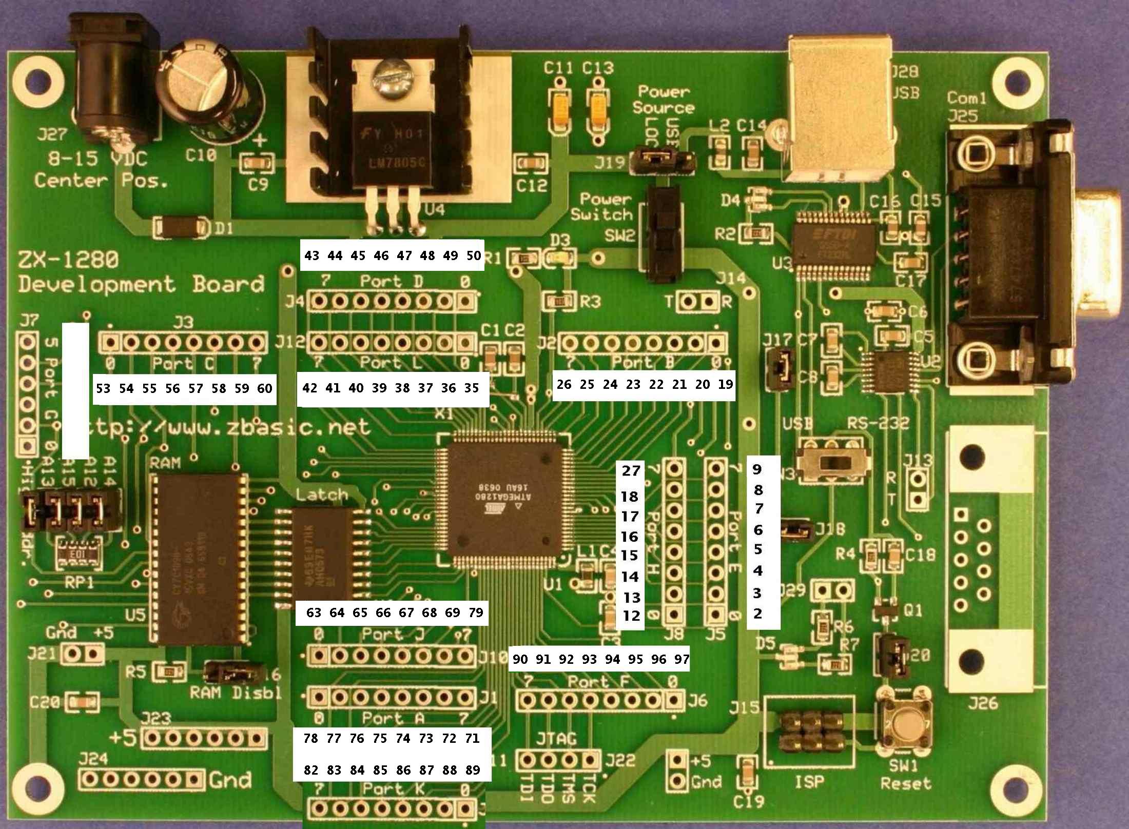
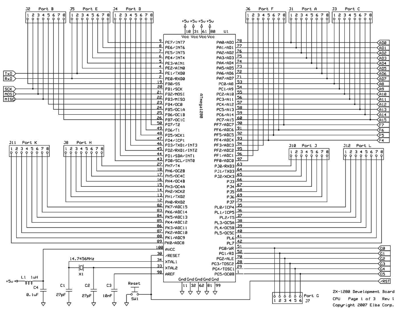
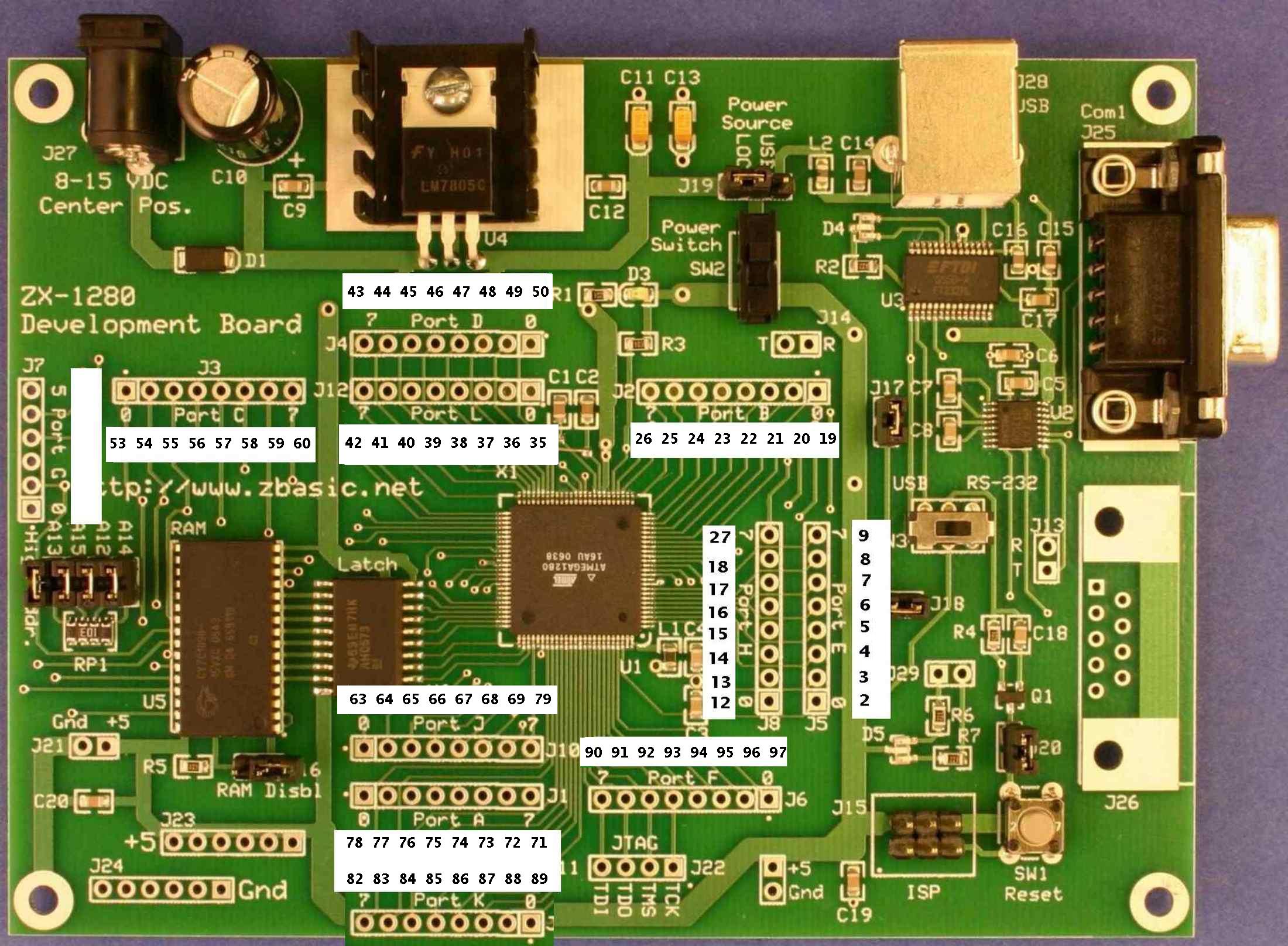
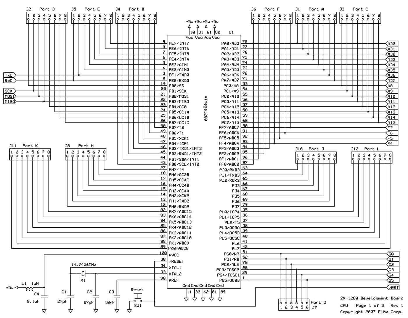
The processor can read two 8 bit par. ports much faster than any serial
port. We have over 100 pins on the processor with something like
80 I/O bits. We have pins to burn. The built in counter is inaccurate
due to the high level programming language. See jitter in the ZBasic forum.
The unit is mounted in the cockpit so if the pilot can stand to fly it
the regulator will be happy. The CMOS will be happy with +/- 1 volt.
We need to adjust the osc for the number of teeth on the flywheel
which varies. Timing caps are a lot more stable than they used
to be. The CMOS version of the 555 is head and shoulders more stable
compared to the old version.
My experience with CMOS is very positive and I have been using
them like this for 40 years. The rise time is slower so they generate
less noise in the frequency range we use them in. HC and HTC is a waste.
Redesign the board to fix the problems and I will take a look.
Paul Lamar
--
The Rotary Engine NewsLetter. Powered by Linux.
ACRE NL web site.
http://www.rotaryeng.net
Youtube key word PaulLamar2
Copyright 1998-2010 All world wide rights reserved.