Please look this over carefully and if you
see any mistakes please let me know.
Paul Lamar
Paul,
I'm new.
What layout software are you using, ExpressPCB?
You are running traces at odd angles. I prefer to keep the angles on my
boards evenly divisible by 45. It's easier to keep track of the signals.
You have pads for parts in the middle of traces; for example your larger
caps (I assume they are caps; you have no reference designators or part
numbers showing). Try to avoid this wherever possible; the trace wicks
the
heat away while you are trying to solder the leads, and you will be much
more
likely to "lift" the pad and destroy the board. By "lift", I mean
breaking
the bond between the FR4 fiberglass and the copper. Once the bond has
been broken, the board is scrap.
I do not know why you are using such thin traces. It costs no more to
have boards made that have nice fat traces. Narrow traces will be more
easily
damaged, and much harder to repair. Just make certain you have 8 mil
separation from things that are not supposed to be connected. I run the
widest
traces that I can while maintaining 8 mil separation.
I do not know what ICs you are using, but I do not see sufficient bypass
capacitors. The "rule of thumb" is a minimum of one 0.1uF (100nF) metal
poly or ceramic bypass capacitor per IC, as close to the power pins as you
can
get them. It is also advised to use bypass capacitors sprinkled liberally
between the power and ground buses aka "rails" around the board. If you
don't do this, you may regret the omission later.
You are far better off to include pads that you don't need, than try to
cobble up the board later.
Steve
Yes express PC.
Paul Lamar
OK, I came up with a slightly modified approach for the board.
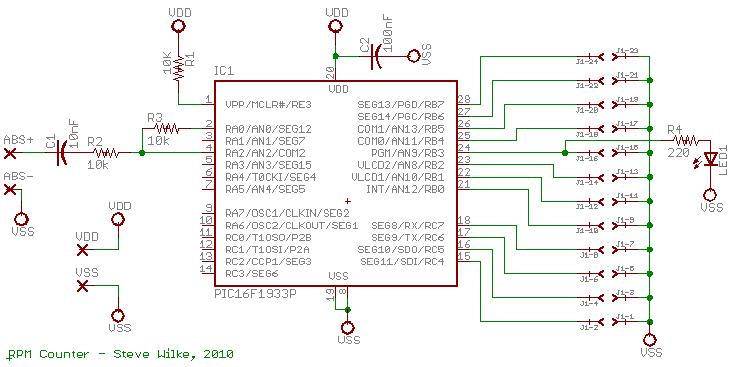
Replace all the IC's with a PIC16F1933 that has the extended temperature
rating. That makes most of the parts simply go away. The PIC itself costs
about $2 if you're buying one at a time.
It will also be more accurate than using a 555 timer, because the internal
clock is calibrated to better than 1% accuracy.
Among many other features, this PIC has an internal comparator that can set
it's own reference level, and has software programmable hysteresis.
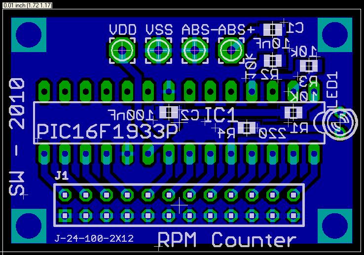
I've attached a preliminary schematic and board layout. Note that there
is no regulator as of yet, but I have a few in mind that are rated for >60v
in. At this point, the board is roughly 1.7" x 1.2". The connector is for
a 24-pin ribbon cable to go to the main board; every other signal is
ground to help keep things quiet.
Your thoughts?
Steve
That will work very well indeed no doubt. In fact I just had a conversation
with a hangar neighbor that has built over 50 consumer products mostly
based on the PIC. That is exactly what he wanted me to do.
In fact it could be made to be interchangeable with my system.
You need a couple of bits so it can communicate with the processor
and tell the processor when it is ready to send the RPM data.
You will also need a way of telling it the number of teeth
on the flywheel. That number varies from engine series to
engine series. That function is done by the pot on the 555.
However it violates the premise that nothing about
this system needs to be programmed in assembly language.
Admittedly the PIC counter asm program is short and simple.
Anybody with a little instruction and with some recent real cheap
($30) USB high speed data acq systems now on the market one can trouble
shoot it.
The whole idea here is to eliminate the biggest drawback
to do it your self EFI is the steep learning curve for
asm and C. That is why I am going with BASIC. If one wanted
to learn asm the Megasquirt system could be reworked to better
work with the A/C rotary.
As soon as you make an open source system easy and quick to program
the expansion capabilities and user interface ideas are limitless.
Paul Lamar
--
The Rotary Engine NewsLetter. Powered by Linux.
ACRE NL web site.
http://www.rotaryeng.net
Youtube key word PaulLamar2
Copyright 1998-2010 All world wide rights reserved.