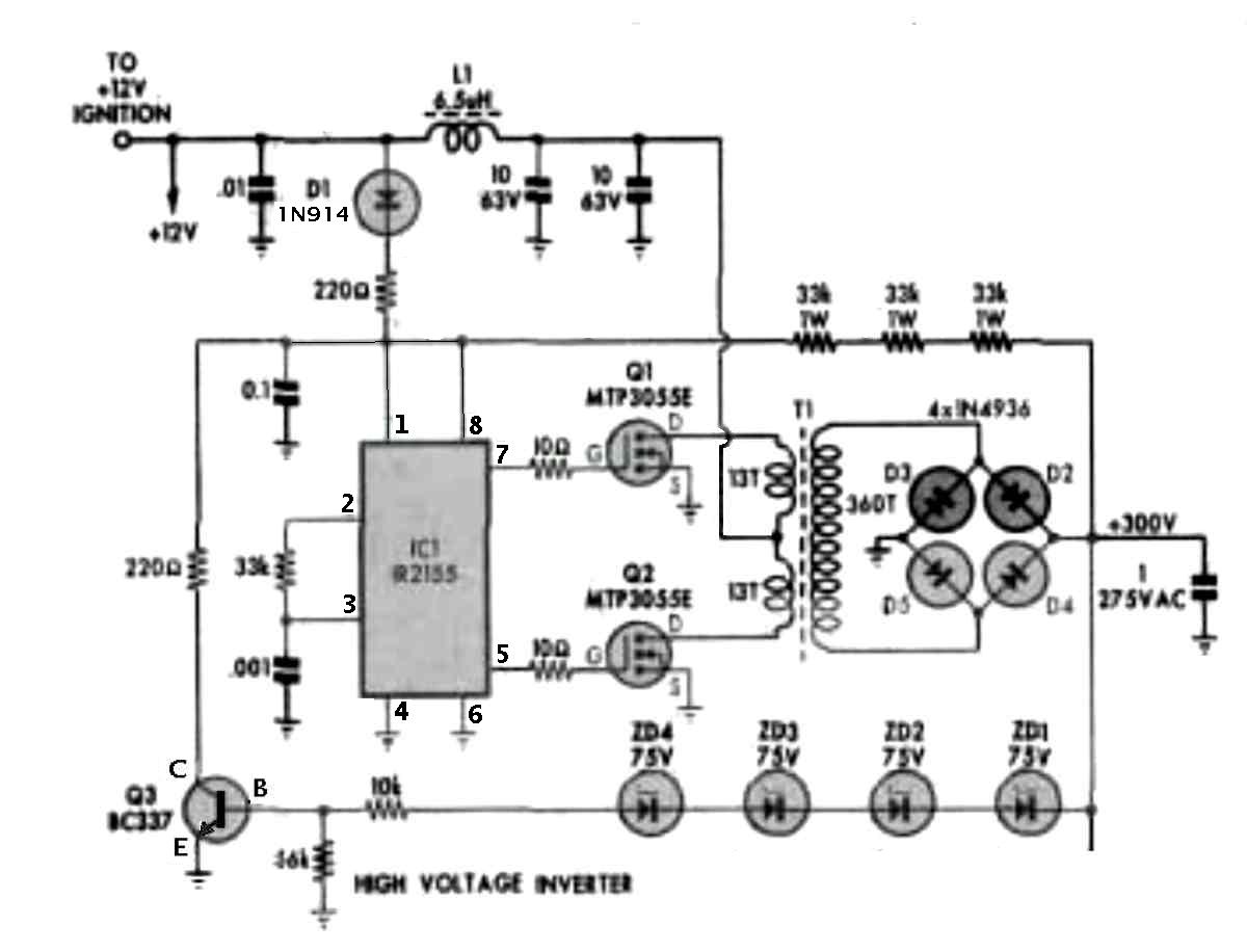
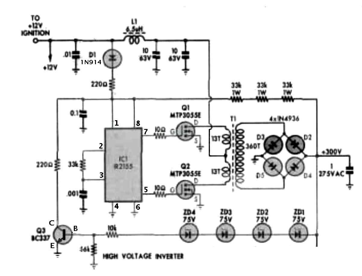
Got the Aussie system set up on the bench. The power supply
does
not appear to be oscillating so far. No current drain :(
Paul Lamar
Paul
On the Aussie ign there is probably a 2nd connection
for +12V switched that needs to be powered in addition to the main + input.
regards Robert
I had the trigger signal connected to the wrong terminals.
The PS osc does not run when the engine is stopped.
This thing is AWESOME!!!!. My wimpy 12 volt power supply dropped
off to seven volts at 3 amps and still the spark is jumping
1/4 of an inch at 250 sparks per second or 15,000 RPM for
a one rotor. 7500 RPM for a two rotor It starts to miss
about 16,200 RPM for a one rotor but that could be
the power supply. Only 21 watts input power. The stock 2nd
gen coil is running cool as a cucumber.
I have a USB router with a 2 foot cable on my notebook
computer in close proximity and Windows is going crazy thinking
I am plugging and un plugging USB devices. Linux is too smart
for that :)
I think Aden Lindsay sent this to me from Perth years ago
and I am just getting around to testing it. Thank you Aden.
This is the system we will copy. Only two for each spark plug
might work instead of four I had first thought.
Next thing is to get the bigger power supply hooked up.
Paul Lamar
----------------------------------------------------
Nice photos!
I have to caution you that operating the CDS system on low voltage is
risky. The power MOSFETs that drive the primary of the push-pull DC-DC
converter's transformer need to have a Vgs (voltage on the gate with respect to
the source) of 10v in order to turn fully ON. As the input voltage drops,
the power dissipation in the MOSFETs will increase, due to the increased
Rds(on). (Rds=resistance from the drain to the source terminals.) If the power
dissipation becomes excessive, the MOSFETs will self-destruct.
You will need to look at the datasheet for the particular MOSFETs in
question to find the Id (drain current) vs Vgs plots.
While you are testing it, I suggest that you ensure that the input supply
does not drop below 10v. Even if you don't fry the MOSFETs during testing,
you may subject them to significant and abnormal thermal stress which will
have an adverse effect on their service life.
Let's talk for a moment about the gap you're using for the spark.
It is generally accepted that to ionize a 1 meter air gap at sea level, 3
million volts are required.
You can extrapolate downwards, and say that it requires 3,000 volts to jump
a 1mm gap at sea level; 1mm being roughly 39.4 mils (thousands of an
inch).
However, your engine has a compression ratio. I don't know what your
engine's compression ratio is offhand, but let's just assume 12:1 for the
moment. Since you're testing in open air at (roughly) sea level, you will need
to multiply the distance of the gap you will be using by the compression
ratio of the engine, plus some if you wish to see what it'll do with worn
spark plugs.
So, if your standard spark plug gap is 39.4 mils, and you have a 12:1
compression ratio, you will need a gap of 473 mils (0.473") in order to simulate
the spark gap while at 1 standard atmosphere. It will require 36kV to
ionize the air in that gap. If you wish to test under more adverse
conditions (say, worn spark plugs) then increase the gap by 5% to 10%.
Note that the shape of the electrodes used for the spark gap will have an
effect. If you use electrodes with conical points, the air will ionize
more quickly. If you use a cylindrical rod (like brazing rod or brass/copper
wire) with the end chopped off cleanly, you will more accurately simulate a
fresh spark plug. If the shape is rounded (half-spherical) you will
better simulate a worn plug.
I suggest that using a chuck key in your spark tower for a test is not
doing it any favors. Even though the test was of relatively short duration,
you may have caused some arcing/pitting in the coil tower, which will
accelerate wear. For best results, you should use an ignition wire of the type
you will be using on the aircraft to minimize wear and tear on the coil.
Regards,
Steve Wilke
You must be clairvoyant Steve. I blew it last night when I was fooling with
the power supply current limiter. Do you think it is the FET's?
I have it apart to fix it.
The MTP3055E TO-220, N-channel MOSFETS, (Q1,Q2), 14A at 60V was
used and may no longer be available.
Can you suggest a better one?
Paul Lamar
--
The Rotary Engine NewsLetter. Powered by Linux.
ACRE NL web site.
http://www.rotaryeng.net
Youtube key word PaulLamar2
Copyright 1998-2010 All world wide rights reserved.