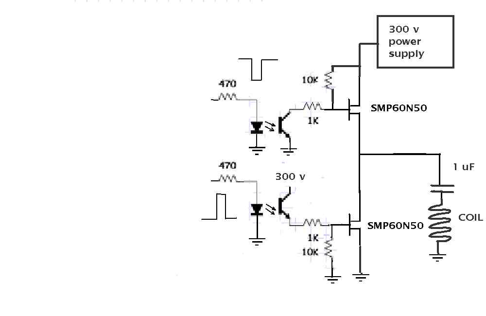
Dead time is the time between when the top FET switch is
turned off and the lower FET switch is turned on.
These are called totem circuits, push me pull me
or huff and puff if it is a tandem engine airplane :)
Normally this is controlled by and can be adjusted
by the designer in the half bridge driver chips.
It is like you have to turn off the front engine
before you start the rear engine.
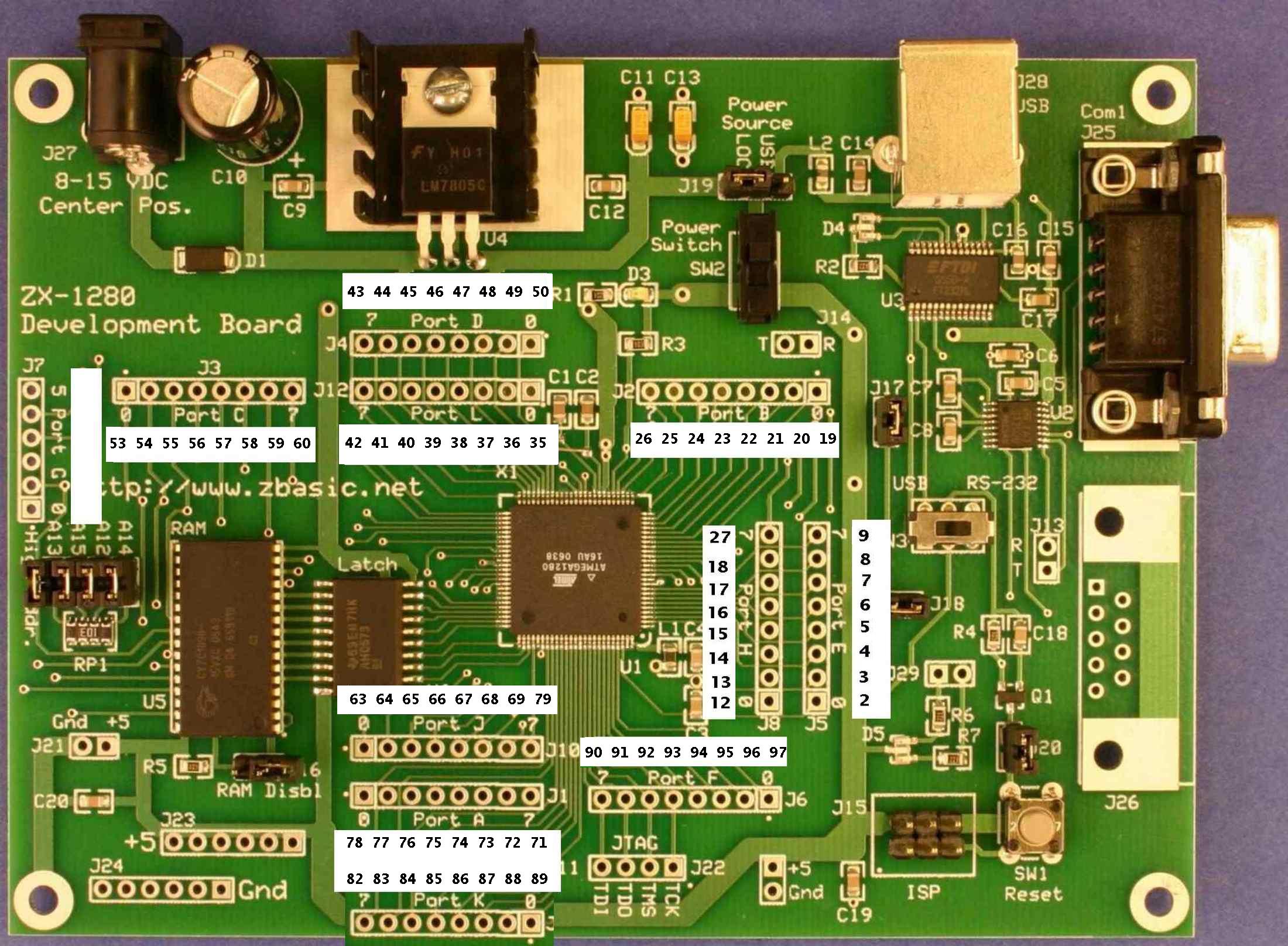
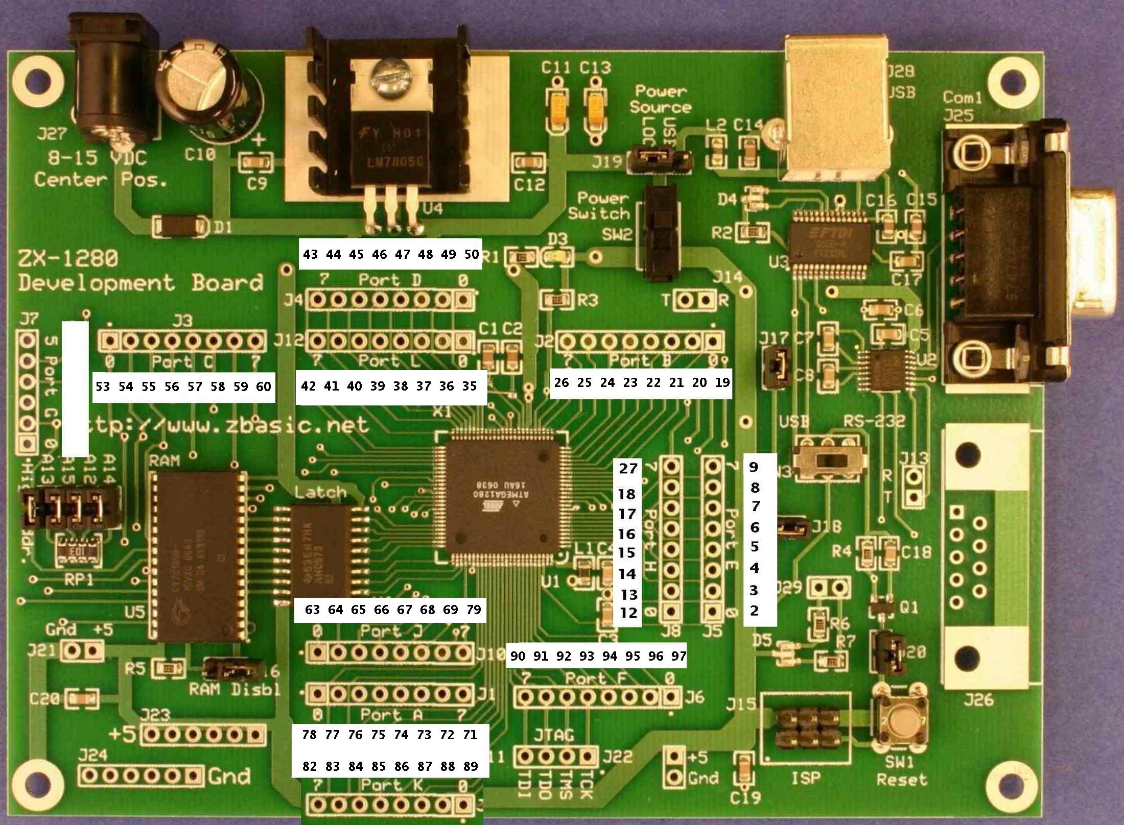
I am using the AtMel ZBasic computer and opto couplers
to simulate a half bridge driver chip. With the computer,
the dead time can be anything controlled by the software
but in this case I am using just a few micro seconds.
Half bridge driver chips are normally used for
switching power supplies that can oscillate at up
to 100K Hertz (cps). Me and the Aussies are using
them in a different way for capacitor discharge
ignition systems. The top FET switch is on the vast
majority of the time to charge the capacitor.
When you need a spark, the top FET switch is turned
off and the bottom FET is turned on for the length
of time it takes the cap to discharge through
the lower FET and the coil. Usually less than 100 micro
seconds. Then it is turned off and the top FET turned on.
Here is the software to do that.
===================================================
Public x as long
Public y as long
Sub Main()
for x = 1 to 100000000000 'keeps running until
Debug.Print CStr(x)
Call PutPin(12, ZXOutputHigh) 'top FET CD 1 on
for y = 1 to 1000 '.......... .roughly 2.5 ms
next y '...................... combined with debug.print
Call PutPin(12, ZXOutputLow) 'top FET C1 1 off
for y = 1 to 5 '............... dead time
next y
Call PutPin(13, ZXOutputHigh) 'lower FET CD 1 on
for y = 1 to 50 '............. stays low for 100 uS
next y
Call PutPin(13, ZXOutputLow) 'lower FET CD 1 Off
for y = 1 to 5 '............... dead time
next y
Next x
End Sub
================================================
The last thing you want to have happen is both
FET switch's on at the same time. Our new 300 V power
supplies have a safety feature so they would
shut off if that happened for long. They also
have a low voltage turn off so if the battery
is less than 9 volts you get no ignition.
The up side is your expensive ($150) power
supply is not destroyed :)
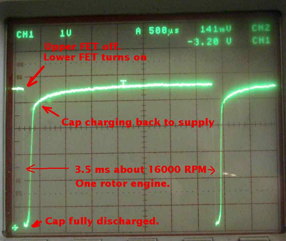
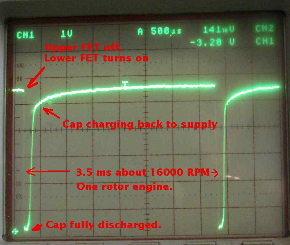
The cap is charging fine at around 16,000 RPM
through a 2.5 ohm resistor simulating the coil.
The Mazda 2nd gen trailing plug coil has
less than 1 ohm DC resistance.
The scope trace shows the voltage at the top
of the cap. As you can see it is the power
supply voltage for the majority of the time.
It goes toward zero when the lower FET is
turned on.
BTW these are SMP60N05 FETs just because I happened
to have a bunch. The lower the on resistance
of the FET the better the ignition will work
and the faster the cap will charge. I can't find
any data on the SMP60N05 so I don't recommend it.
Apparently it is obsolete.
Paul
--
The Rotary Engine NewsLetter. Powered by Linux.
ACRE NL web site.
http://www.rotaryeng.net
Youtube key word PaulLamar2
Copyright 1998-2010 All world wide rights reserved.