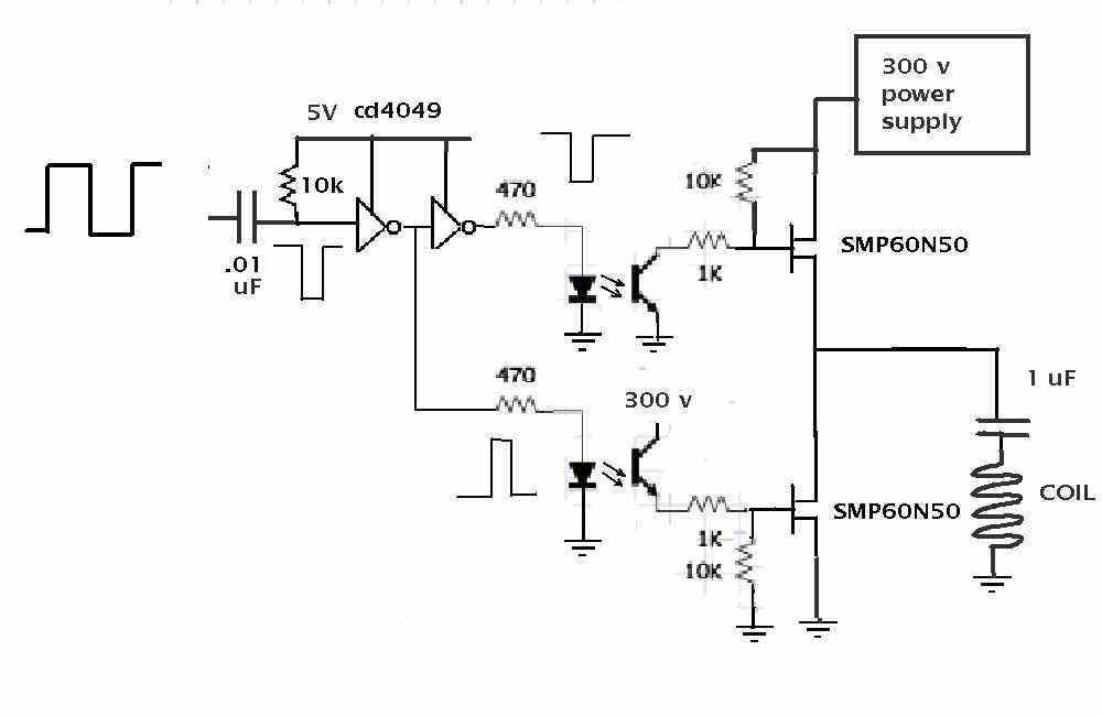
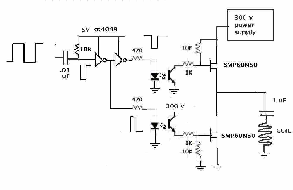
I found this circuit on the web.
http://www.mcmanis.com/chuck/robotics/tutorial/h-bridge/bjt-circuit.html
Seems to work great on 12 volts or so. I used a 1.5 ohm
resistor to simulate the coil. Works to 125 PPS
or 7500 RPM.
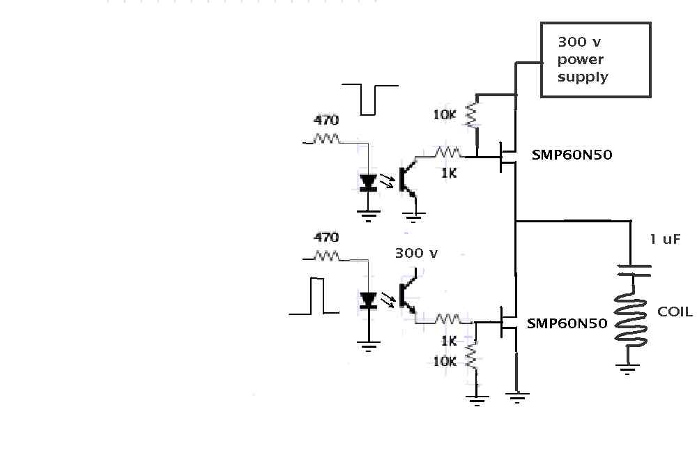
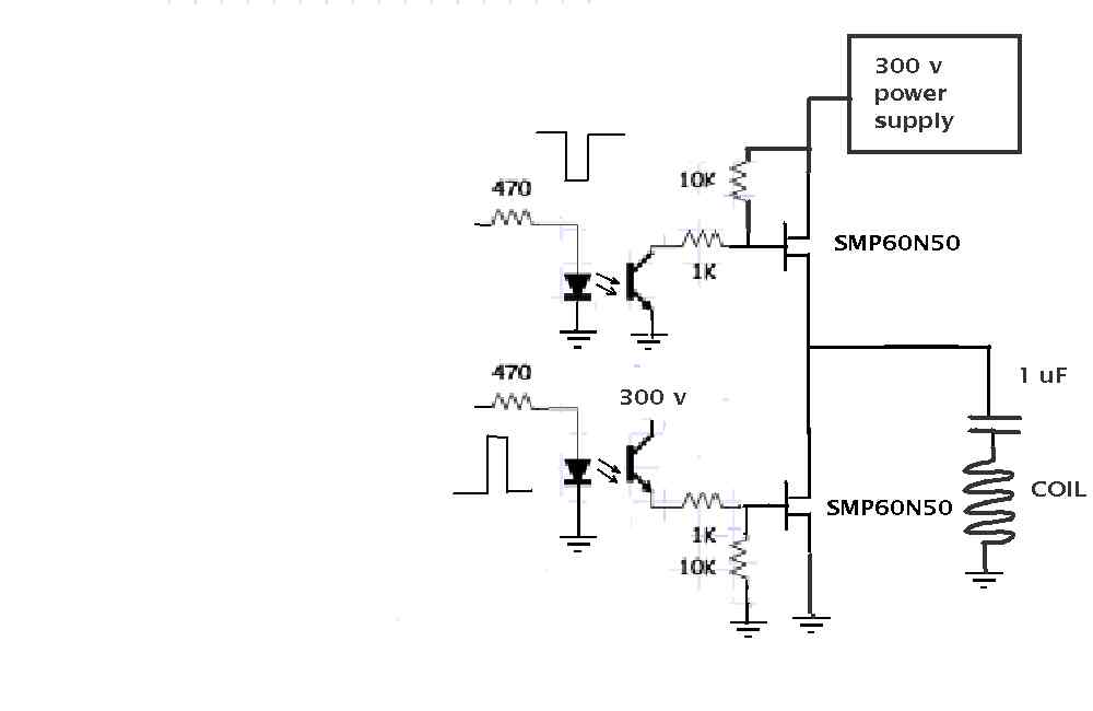
The trick is to use opto isolators to trigger the FET's.
I'll know more when I get the 300 volt power supplies.
Next step is build another one and hook them both
to the same resistor.
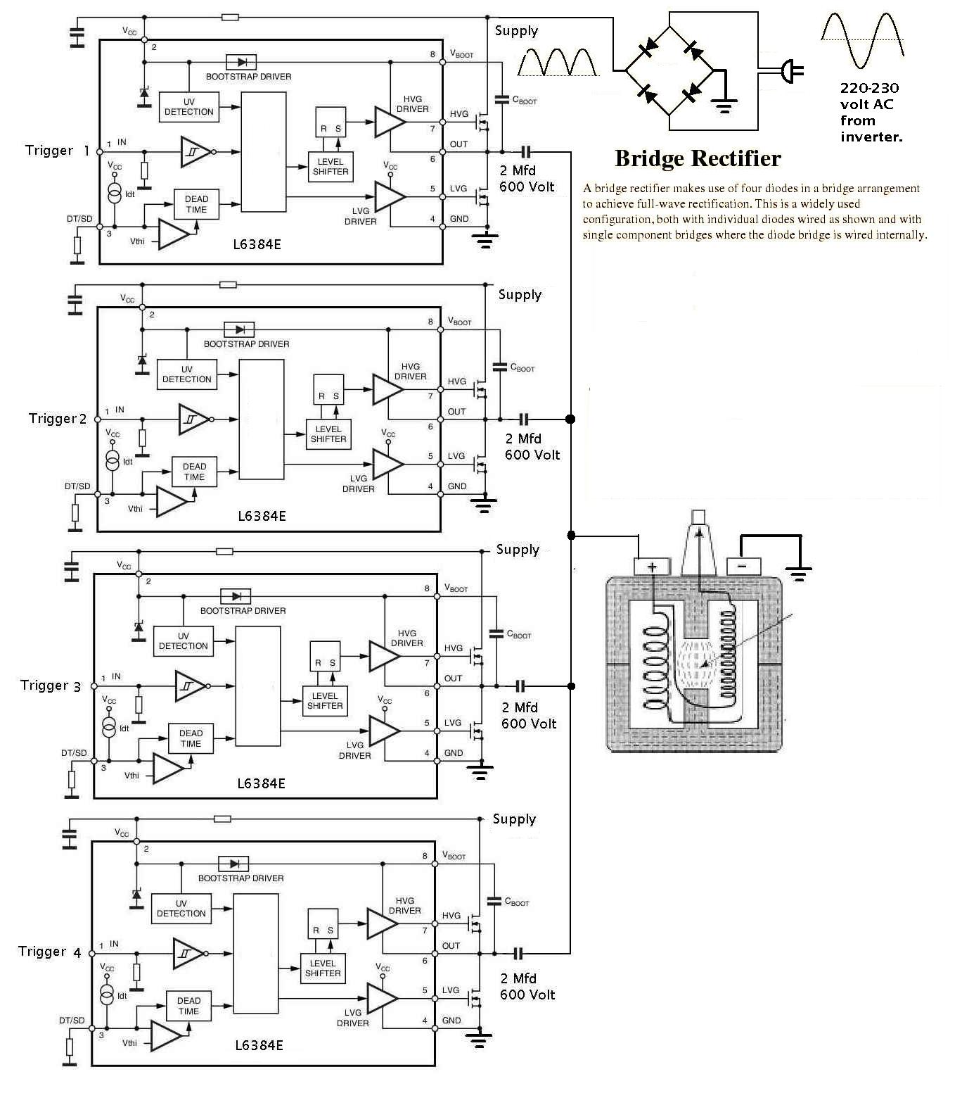
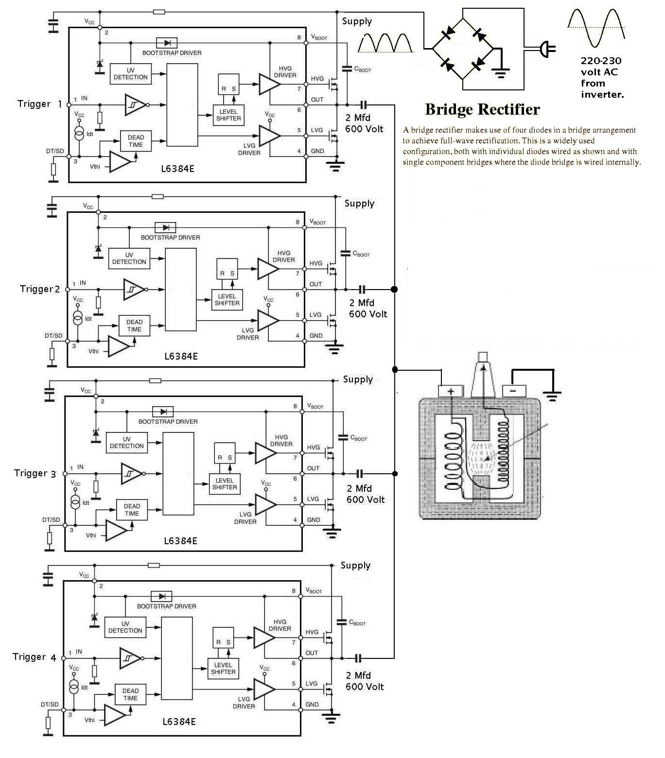
Basically what this does is substitute for the half bridge
driver chip.
-------------------------------------------
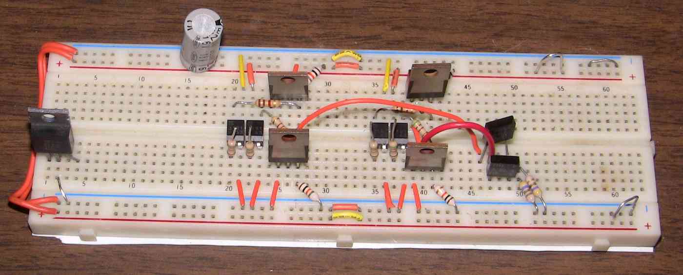
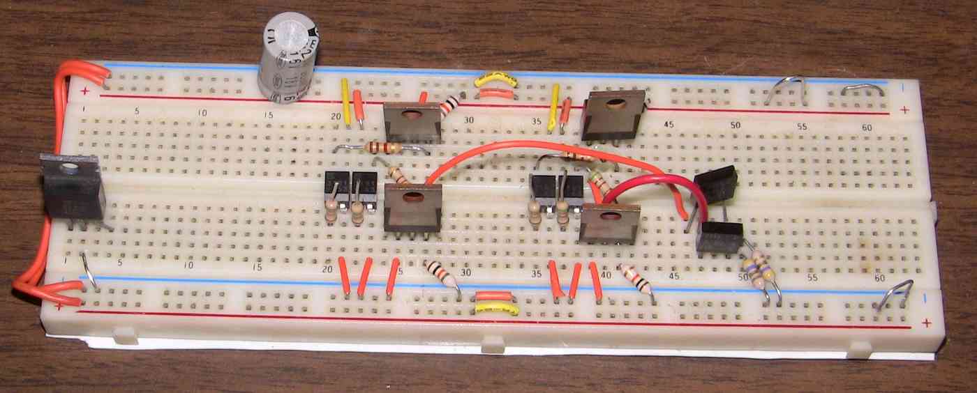
Here is what two CD ignition systems looks like.
Eventually it will be just one but it will fire 10 degrees
apart four times from idle to 8000 RPM in the interest
of a better BSFC. So far rotaries have used piston
engine ignition systems. IMHO not the best as the
combustion chamber is moving past the spark plugs.
I built this dual prototype low voltage version to explore
any possible issues of having multiple 1 uF capacitors
ultimately charged to 300 volts connected to the same
coil. In this case a 2.5 ohm resistor. Better to burn
up parts at this voltage rather than risk $100 high
tech 300 volt power supplies. Also on the way.
That Internet article mentioned above ironically discussed
controlling this with a micro computer which is
what I will do to simulate the final stand alone
system. Each FET switch will be turned on and off
at appropriate times with individual ATMel 1280 bits.
Saves making a Hall Effect trigger PC board which
the final design will use. It also prevents both
FET switches being on at the same time in a totem pole
arrangement like this. That would be an instant
disaster.
I may or may not use the opto's in the final design.
Depends on how easy it is to use the Aussie type
half bridge driver IR2155 chip which is on its way from
God knows where :)
Stay tuned.
Paul Lamar
--
The Rotary Engine NewsLetter. Powered by Linux.
ACRE NL web site.
http://www.rotaryeng.net
Youtube key word PaulLamar2
Copyright 1998-2010 All world wide rights reserved.