Dead time is the time between when the top FET switch is
turned off and the lower FET switch is turned on.
These are called totem circuits, push me pull me
or huff and puff if it is a tandem engine airplane :)
Normally this is controlled by and can be adjusted
by the designer in the half bridge driver chips.
It is like you have to turn off the front engine
before you start the rear engine.
I am using the AtMel ZBasic computer and opto couplers
to simulate a half bridge driver chip. With the computer,
the dead time can be anything controlled by the software
but in this case I am using just a few micro seconds.
Half bridge driver chips are normally used for
switching power supplies that can oscillate at up
to 100K Hertz (cps). Me and the Aussies are using
them in a different way for capacitor discharge
ignition systems. The top FET switch is on the vast
majority of the time to charge the capacitor.
When you need a spark, the top FET switch is turned
off and the bottom FET is turned on for the length
of time it takes the cap to discharge through
the lower FET and the coil. Usually less than 100 micro
seconds. Then it is turned off and the top FET turned on.
Here is the software to do that.
===================================================
Public x as long
Public y as long
Sub Main()
for x = 1 to 100000000000 'keeps running until
Debug.Print CStr(x)
Call PutPin(12, ZXOutputHigh) 'top FET CD 1 on
for y = 1 to 1000 '.......... .roughly 2.5 ms
next y '...................... combined with debug.print
Call PutPin(12, ZXOutputLow) 'top FET C1 1 off
for y = 1 to 5 '............... dead time
next y
Call PutPin(13, ZXOutputHigh) 'lower FET CD 1 on
for y = 1 to 50 '............. stays low for 100 uS
next y
Call PutPin(13, ZXOutputLow) 'lower FET CD 1 Off
for y = 1 to 5 '............... dead time
next y
Next x
End Sub
================================================
The last thing you want to have happen is both
FET switch's on at the same time. Our new 300 V power
supplies have a safety feature so they would
shut off if that happened for long. They also
have a low voltage turn off so if the battery
is less than 9 volts you get no ignition.
The up side is your expensive ($150) power
supply is not destroyed :)
The cap is charging fine at around 16,000 RPM
through a 2.5 ohm resistor simulating the coil.
The Mazda 2nd gen trailing plug coil has
less than 1 ohm DC resistance.
The scope trace shows the voltage at the top
of the cap. As you can see it is the power
supply voltage for the majority of the time.
It goes toward zero when the lower FET is
turned on.
BTW these are SMP60N05 FETs just because I happened
to have a bunch. The lower the on resistance
of the FET the better the ignition will work
and the faster the cap will charge. I can't find
any data on the SMP60N05 so I don't recommend it.
Apparently it is obsolete.
Paul
Paul,
Will it work at 21000 rpm? That would be 7000 rpm on a 3-rotor.
Do you really feed 300v into pin 4 of the optoisolator?
Mark
Good observation Mark.
Not yet. I am not sure feeding 300 volts into an opto
isolator will work but Pansonic claims to have some
350 volt versions. There are some on that DigiKey
page you sent me down near the bottom. (attached)
However the switching time is real slow at 40 us.
That could be a show stopper for the opto version.
Not for the half bridge driver version however.
The current test rig is running on 8 volts.
Regarding this on a 32 rotor:
Maybe with better FETs but you would need a distributor
if you are using only one CD system with one coil.
You could make a distributor that worked off the nose
of the e-shaft. Or get a pre 1989 Mazda distributer.
As I recall those were two levels with two spark rotors so
even those required two ignition systems with two coils.
The real early models, back in the 70's, had two entirely
separate distrubtors. Fortunately by the time
the 3 rotor came out in the early 90's electronic ignition
and CAS's came in to use.
My vision is one of these for each leading plug
and something else for the trailing plugs. So they only
need to go to 7500 RPM.
Paul Lamar
Paul,
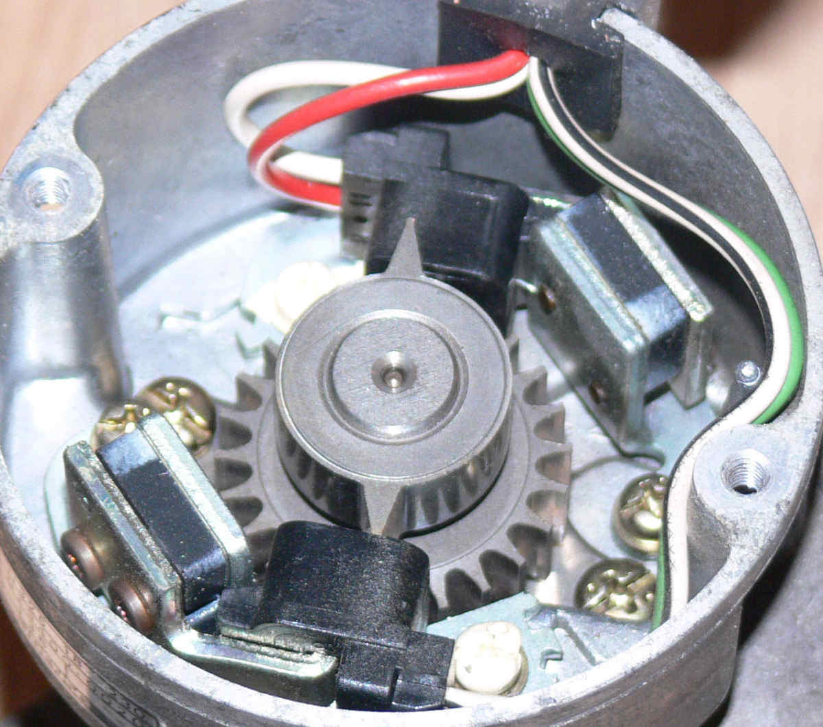
With a little finessing, you can fit three CAS pickups spaced 120* apart
into a 20B CAS housing. That's how I'm triggering the three MSDs that I am
now running. The CAS rotor turns at 1/2 engine speed, but there are two
pointers. So, one of the pointers will align with one of the pickups every
120* of crank rotation. Works for me.
Mark
Mark
Good work Mark. Cool.
So that was the original system you flew with before the RX8
trigger wheel? So Tracy redid his software or you don't use his
ignition wiring? I am glad you have some base line
fuel burn with that system.
Looks like it will work fine. At that diameter one must be careful
to get it at the exact angle. Did Bob set it up on his rotary
table?
I'll do some thing similar for the nose of the e-shaft
as soon as I get the multi-strike going except I will
need only one magnet and it will be larger in diameter
easing the angle problem.
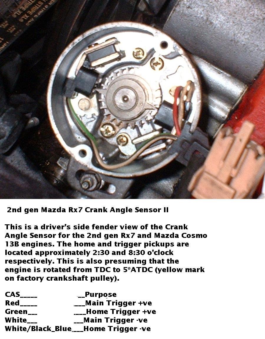
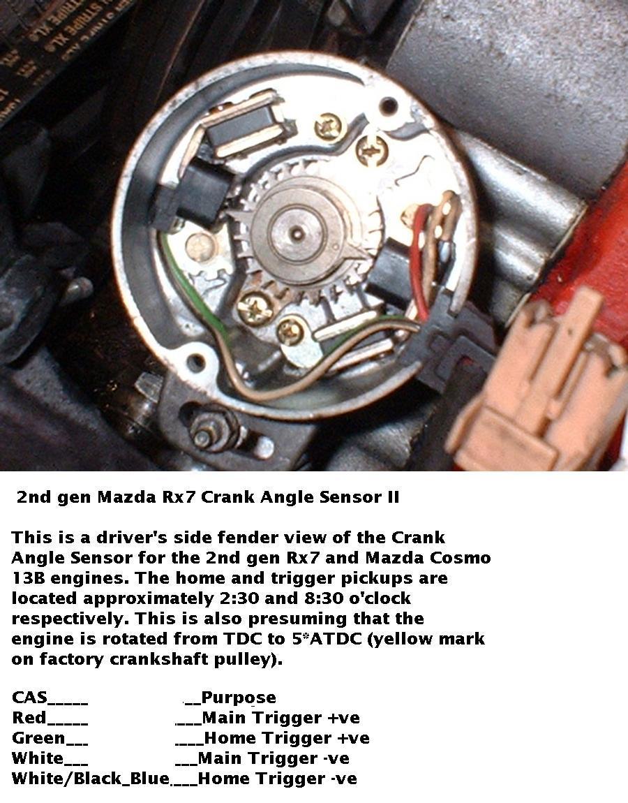
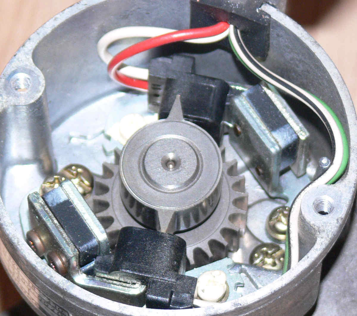
Here is a picture of a stock 2nd gen CAS.
Got any pictures of your modification?
Is the high speed miss now gone?
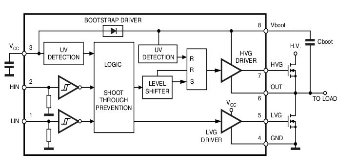
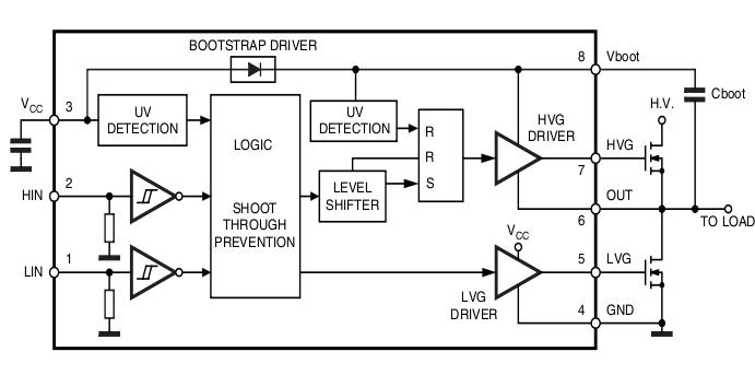
BTW I think I found the ideal hot tip part. It has individual control
for both upper and lower FET. Just like the opto version but
no worriies about high voltage opto's. It is called the L6388E.
If anything it is simpler to use than the L6383E I have now
and the IR2155 used in the Aussie system.
Here is the pdf and jpg for the L6388.
Paul Lamar
--
The Rotary Engine NewsLetter. Powered by Linux.
ACRE NL web site.
http://www.rotaryeng.net
Youtube key word PaulLamar2
Copyright 1998-2010 All world wide rights reserved.