Finally I hope.
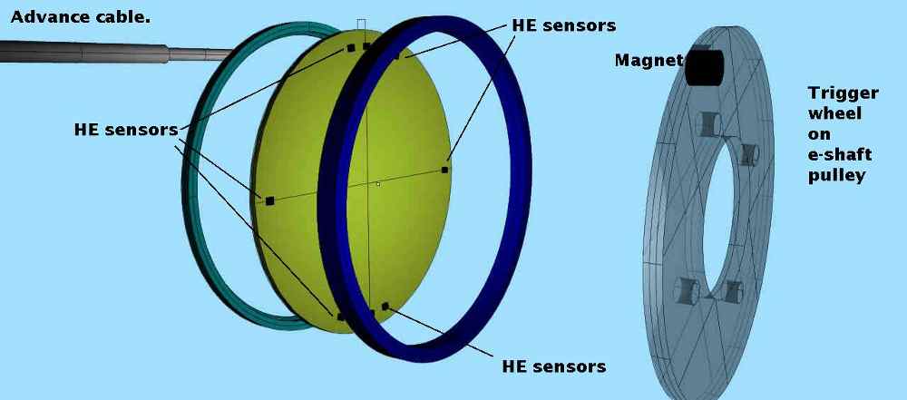
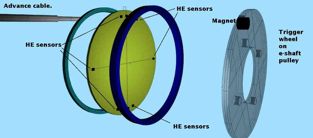
This is designed to fire a spark plug every
10 degrees or so of e-shaft revolution
at all RPM's up to 11,000. Hopefully this
will improve the BSFC about 3 to 5%.
It should work particularly well on racing
engines as they have peripheral exhaust
ports rather than the side exhaust ports of
the RX8 engine. More of the fuel should be burned
in the RX8 engine as well perhaps yielding a
slight increase in power.
The rotary engine is a moving combustion chamber
engine while a piston engine combustion chamber
is stationary. The rotary engine combustion chamber
moves past the stationary spark plugs. The trailing
part of the chamber has a rich mixture if not
raw unburned fuel.
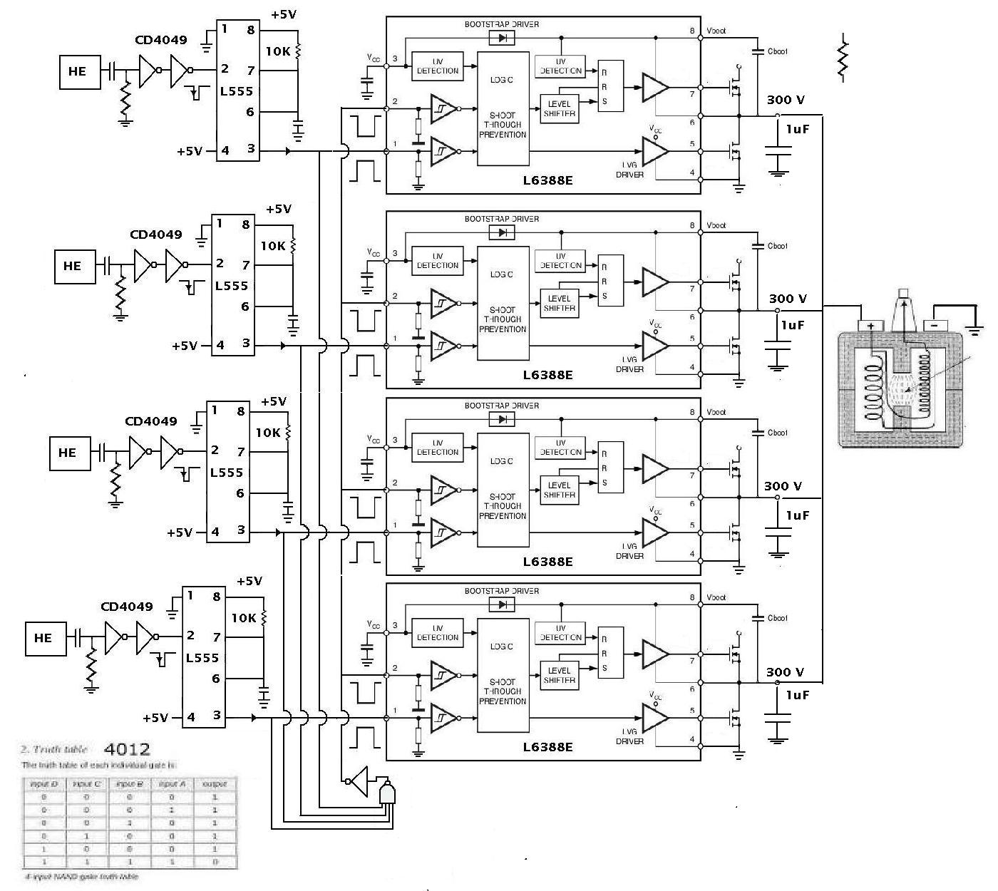
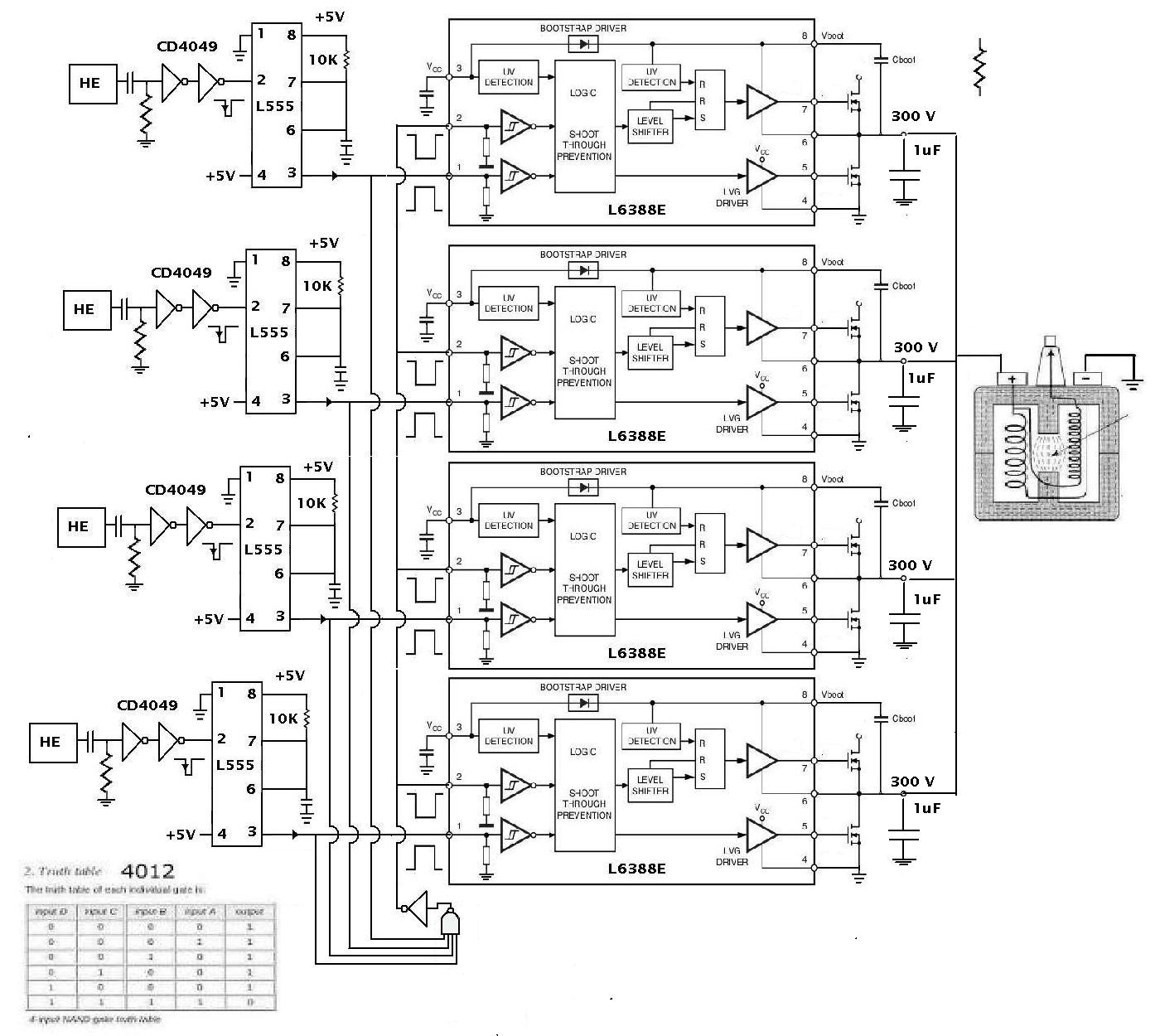
The digital logic became simple once I decided
to cut off all capacitor charging
when any one capacitor is discharging
through the coil. All upper FET's are off
when this happens. That also allows only the cap
selected to discharge through the coil as
all others are totally disconnected.
Other caps cannot discharge as the hot end
is disconnected.
Only a little charging time is lost.
The ST L6388 was the other
logic simplifier as it got me individual control
over top and bottom FET's.
The ST L6388's should be in the first of next week.
The other issue is the characteristic of the
hall effect sensor. At low RPM the trigger
pulse is wide as the magnet spends more time
in front of the sensor. At RPM the pulse
gets narrower. I needed a way of controlling
the pulse width as the capacitor discharge time
is always the same regardless of the RPM.
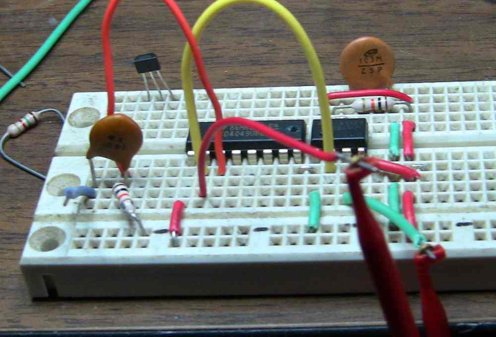
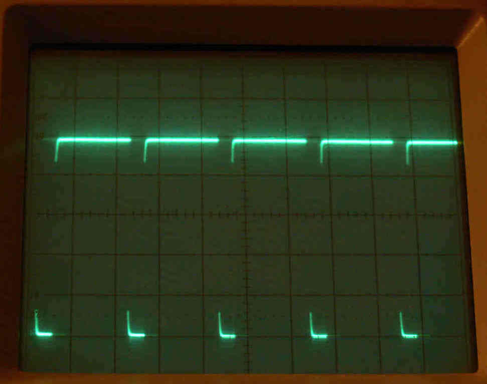
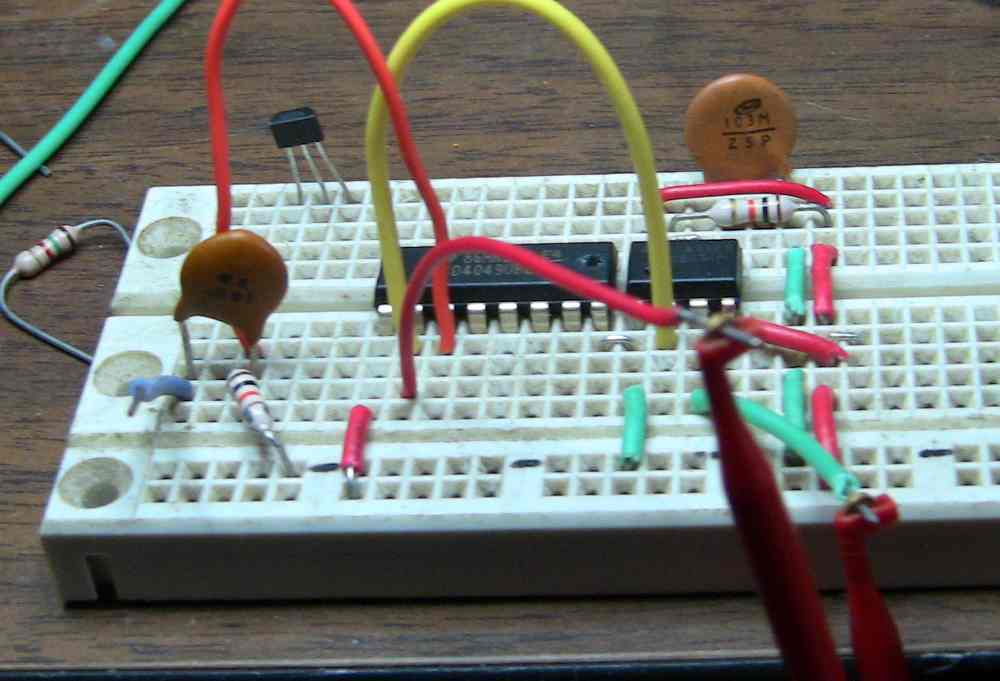
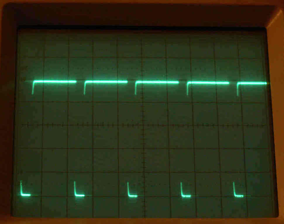
So I added a CMOS 555 one shot on the front end
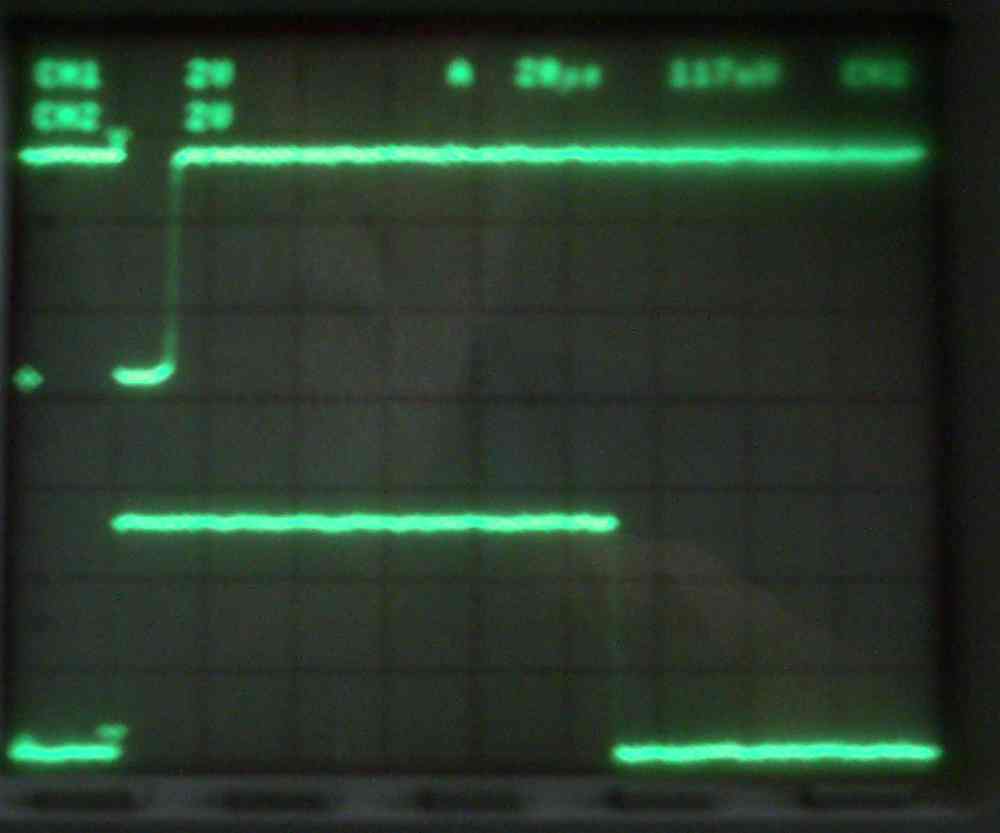
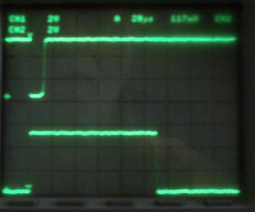
that puts out 100 usec pulse regardless of the RPM.
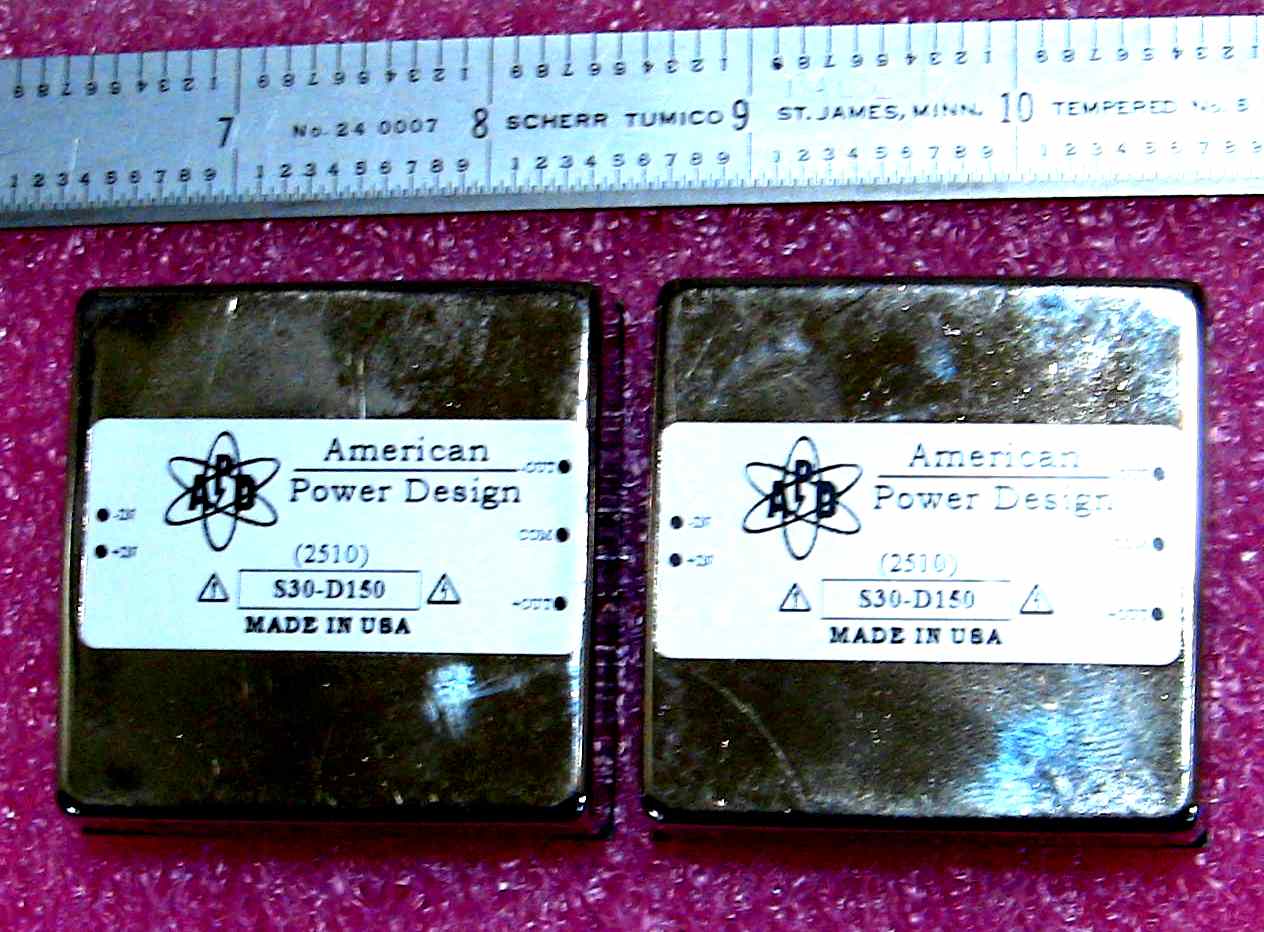
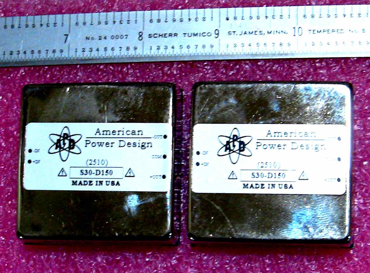
Here is a picture of the scope trace and
the cute little 300 volt 30 watt power supply
from A Power Design. One P.S. per four caps.
This is a one spark plug one rotor unit.
Add units depending on number of spark
plugs and number of rotors. In other
words it is modular.
It looks complicated but the parts are
small other than the 1 uf 300 volt
caps. The L6388 is a 8 pin mini dip.
-----------------------------------------------
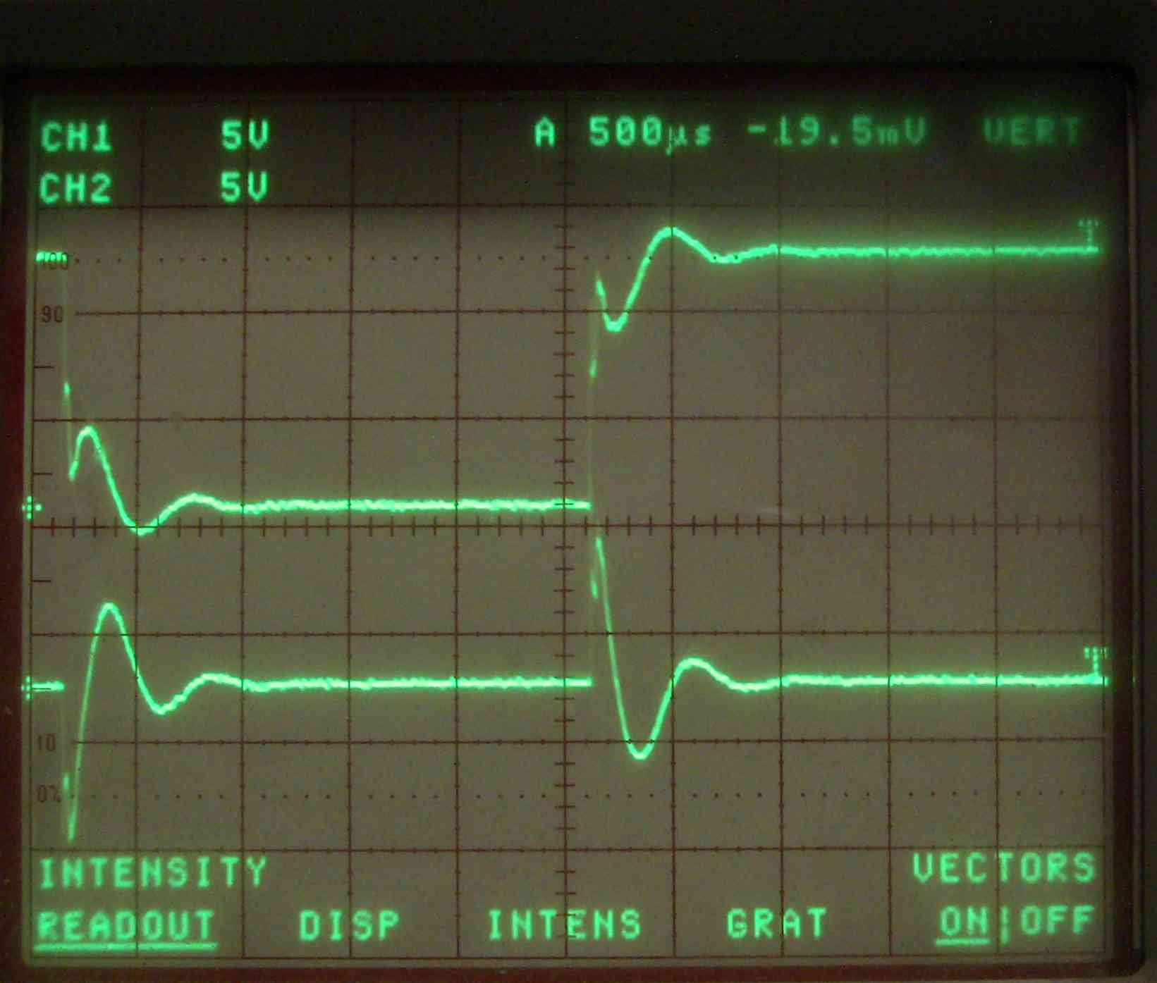
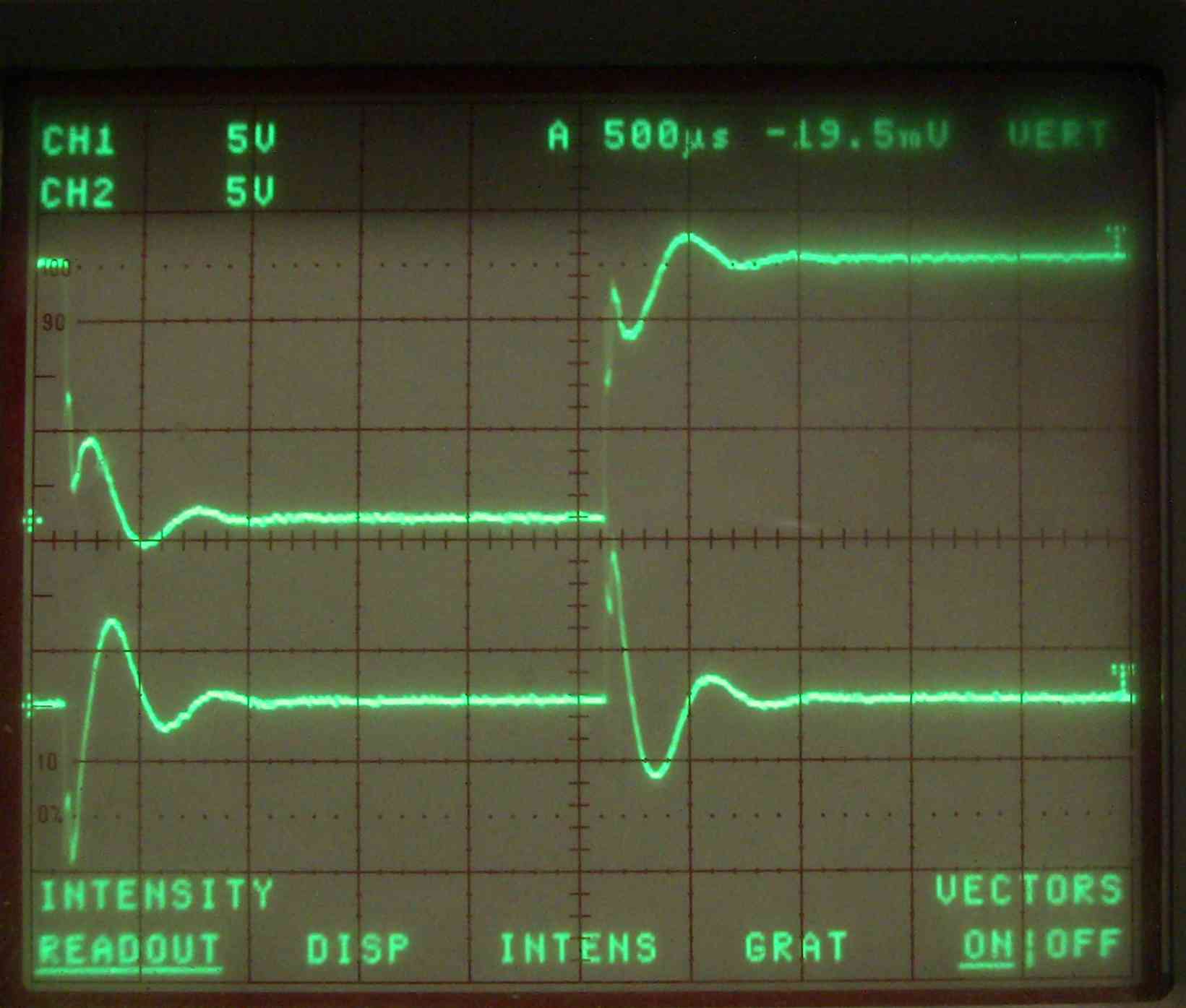
There is a mistake above. Even though the lower
FET switch can close for as little as 100 usec
it may need to stay closed for as long
as 500 usec to allow the coil to oscillate on it's
own in parallel with the 1 uF cap. This in effect
widens the spark. The resistance of the FET
plays a major role in how long this oscillation
goes on. In other words the resistance of the
FET acts as a damper. Also there is a diode in
the FET that plays a role in this oscillation.
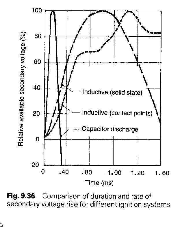
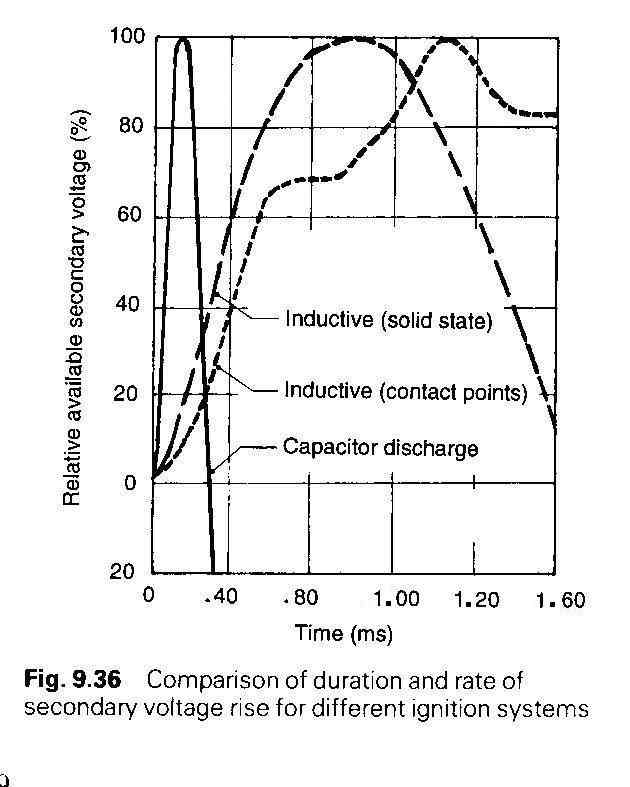
Here are a couple more jpgs on the subject.
The CMOS one shot can be adjusted to optimize
the on time.
At 10,000 RPM we have 6 msec or 6000 usec
between sparks so there is plenty of time
for the cap to recharge.
Paul Lamar
--
The Rotary Engine NewsLetter. Powered by Linux.
ACRE NL web site.
http://www.rotaryeng.net
Youtube key word PaulLamar2
Copyright 1998-2010 All world wide rights reserved.