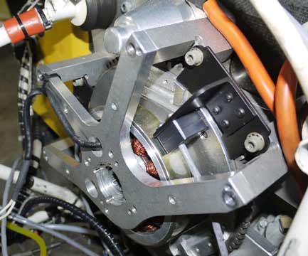
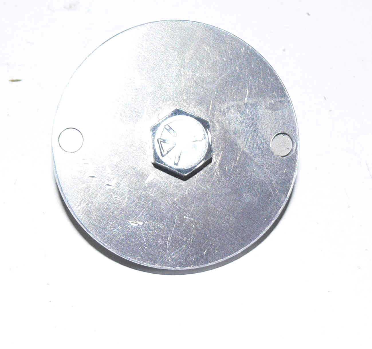
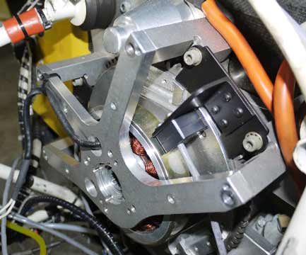
This can be rotated manually like a Model T
to set the timing. It needs a few minor additions.
The CMOS buffers and CMOS 555's are on the board
because there is room for them.
I am working on a dwg for the trigger wheel.
----------------------------------------------
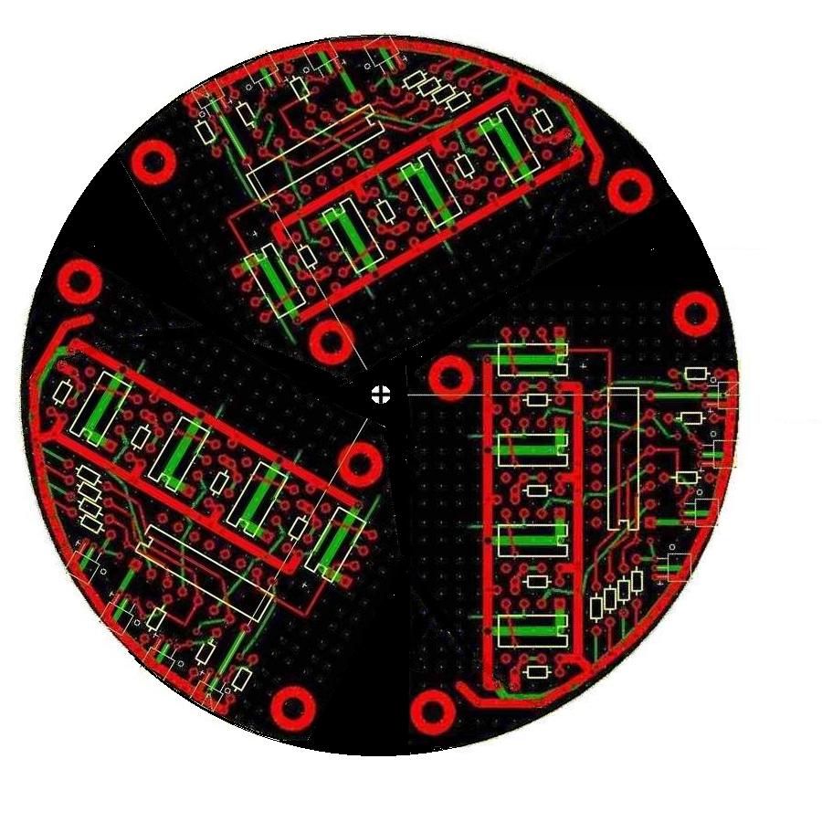
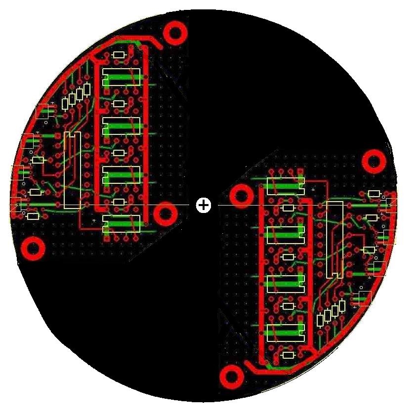
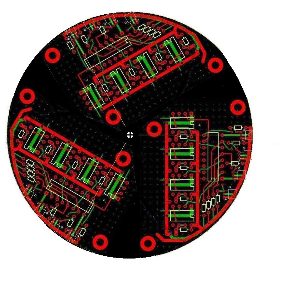
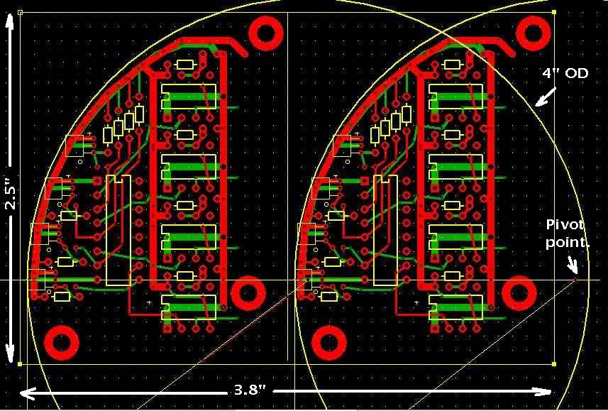
I spent a couple of days redoing the trigger PC board
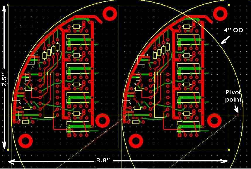
design to save money and make it modular. ExpressPCB
charges $51 for three boards 2.5 inches by 3.8 inches.
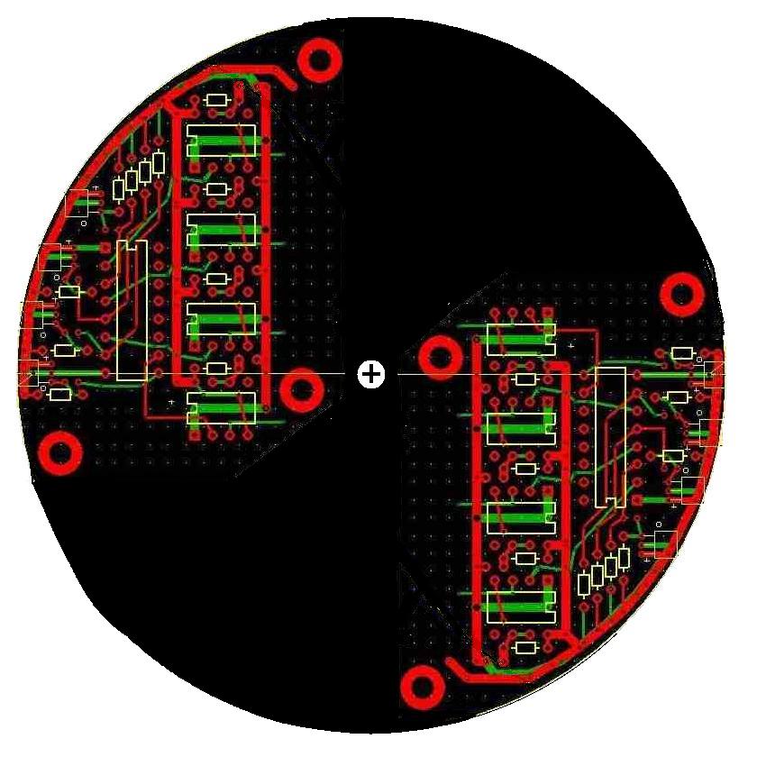
I was able to cram two 120 degree trigger modules on each
board for a total of six for $51 dollars plus
tax and shipping. That is enough for two 3 rotor
engines or three 2 rotor engines. The OD is still
four inches and not five as I at first thought
I would need. Most pulleys on the nose of the
e-shaft are about 4.7 inches in diameter with
some as large as 5.8 inches for the AC probably.
I think I can get the whole unit inside a 4.5 inch
OD housing.
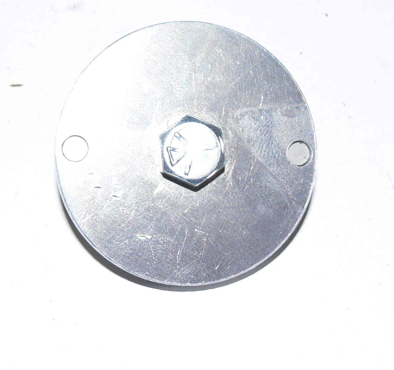
The idea here is they are mounted on an 1/8th inch
thick aluminum plate to pick up certain front
stock cover screws very similar to Klause's Mini Sensor
or Tracy's PSRU adapter plate. Not as large or as heavy.
I am not above stealing a good idea when I see it.
It will be up to the builder to make this plate
for his version of the front cover be it 2nd gen RX7,
3rd gen RX7, 3 rotor or RX8.
Compared to the cost of the PC boards the rest
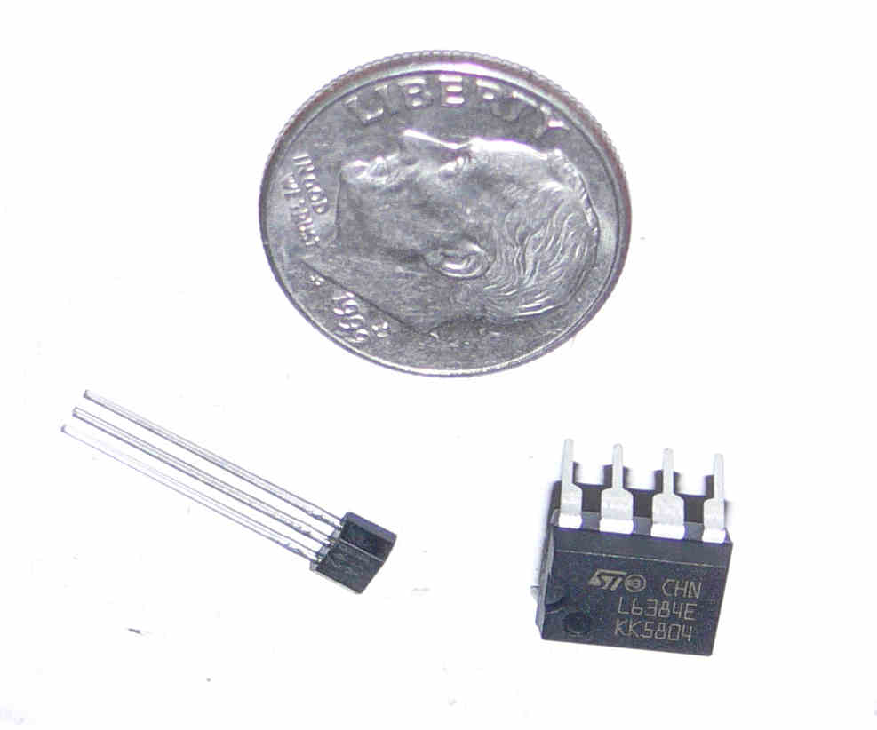
of the parts cost is trivial. CMOS LMC555 cost
$1.23 in quantities of 25. We need four per module.
The CD4050 is 72 cents each. One per module.
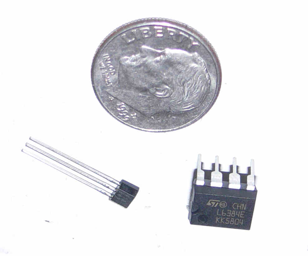
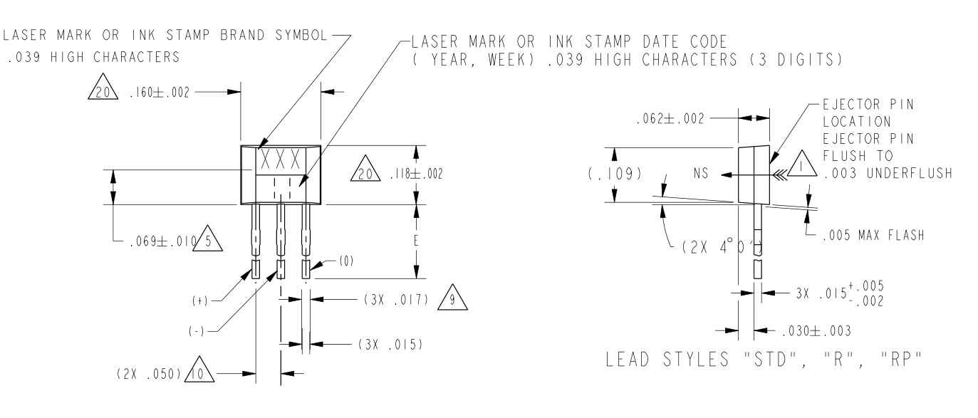
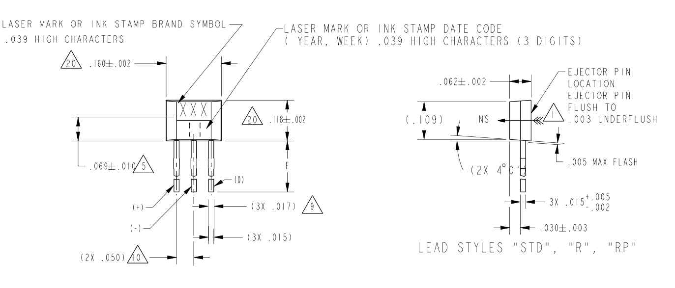
I have not priced the Hall Effect sensors yet.
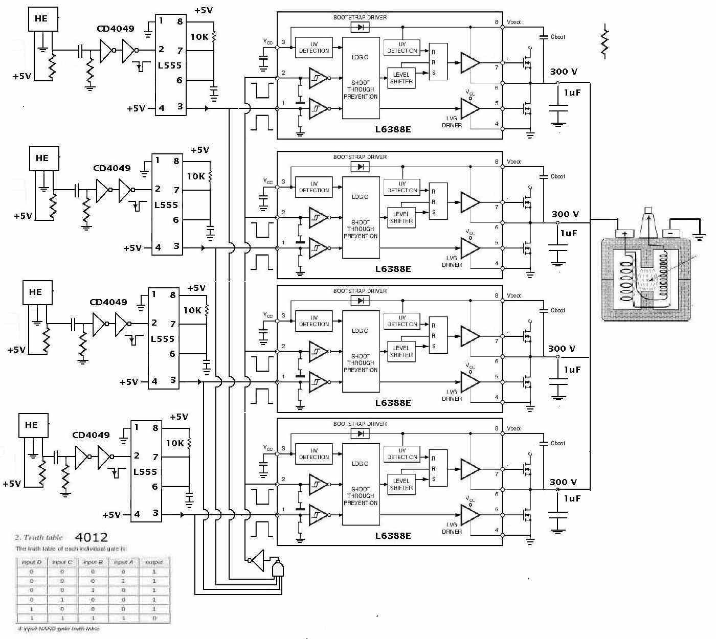
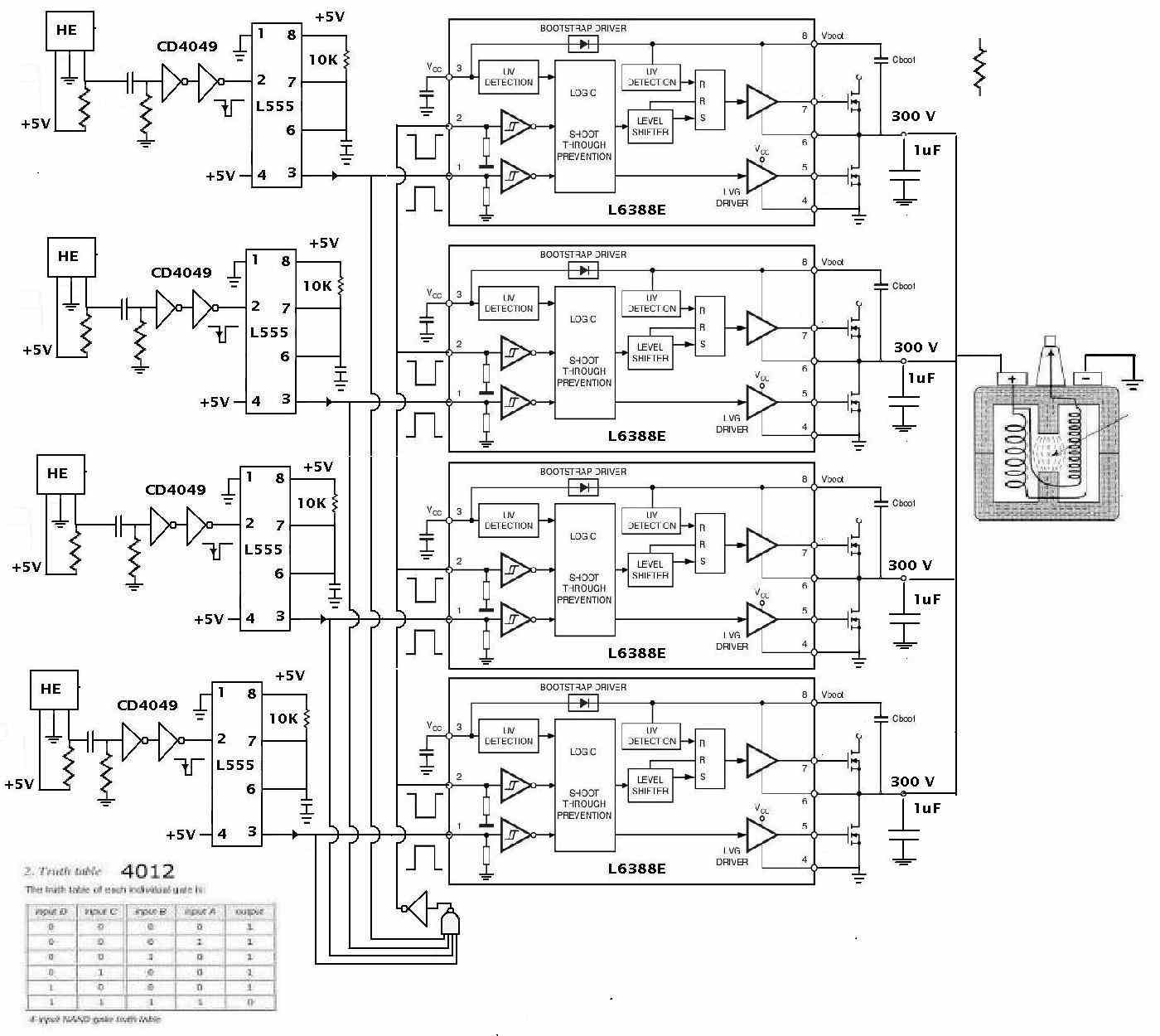
The left half of this schematic is on the trigger
board and the right half on the main ignition module.
The PC board will be covered with silicone conformal
coating.
I sure hope it works. We could use a bit more MPG.
Paul Lamar
--
The Rotary Engine NewsLetter. Powered by Linux.
ACRE NL web site.
http://www.rotaryeng.net
Youtube key word PaulLamar2
Copyright 1998-2010 All world wide rights reserved.