I got the system up and running with the L6388.
Works like a charm.
I never quite understood
why the Aussies were claiming a minimum of two
sparks at high RPM until I looked at the signal
across the 2.5 ohm resister in series with the 1 uF
cap. This resister is simulating the coil,
for now, in the low voltage (12V) test set up.
With 12 volts I am getting a peak current
of .4 AMPS!! through that resistor when the lower
FET turns on and ANOTHER .4 AMPS!! when it turns
off. This is due to the totem pole configuration
of the FET switches. Most CD system use only one
switch.
Imagine what the current would be with 300
volts. Of course the inductance of the coil
will make a difference.
In this set up these two current pulses are 20 usec
apart. The pulse width and timing are controlled
by the ZBasic computer with a simple BASIC
program. RPM is about 9500. The final version
of course will be stand alone with no
computer needed.
Here is a scope picture. The upper
trace shows what the upper FET switch's
input trigger is doing and the lower trace
is the +/- 10 volts across the 2.5 ohm
resister. E = I x R and I = E/R.
In other words when the lower FET
turns on the current pulse in the coil flows
one way and when the lower FET turns off
the current in the coil flows the other way.
Duh!
This means we will have a total of 8 ignition
sparks for each leading spark plug. Groups
of two 10 degrees apart from 22 deg. BTDC
to 10 deg. ATDC. Up to 11,000 RPM or more.
Next step is get the high voltage power
supply and the stock Mazda 2nd gen coil
working. I'll be very surprised and disappointed
if this system does not significantly improve
the BSFC of the rotary.
Hello Paul;
This looks like a nice design. Relatively simple and I
like the pulse pair with each trigger. Even closely
spaced pulses should increase your probability of getting
a good burn started vs a single spark.
But be careful when you choose the 300V supply. Some
quick calculations based on the energy stored/dissipated
in the 1uf capacitor shows that 90mJoules is consumed for
each pulse pair produced. ( energy, in Joules, stored in
a capacitor is CxVxV/2 ) Each of the two pulse pairs
uses the same energy.
At 10k Rev/minute that translates to:
10k/60 pulses/second x 9E-2 Joules/pulse= 15 Joules/second or 15 Watts.
That's for one pulse pair per shaft revolution for one spark plug.
Multiple by the total number of pulse pairs (you always get a pair)
you will use per shaft rotation to get the total DC power you will need at 300V.
Could be a significant amount of power.
Craig Taylor
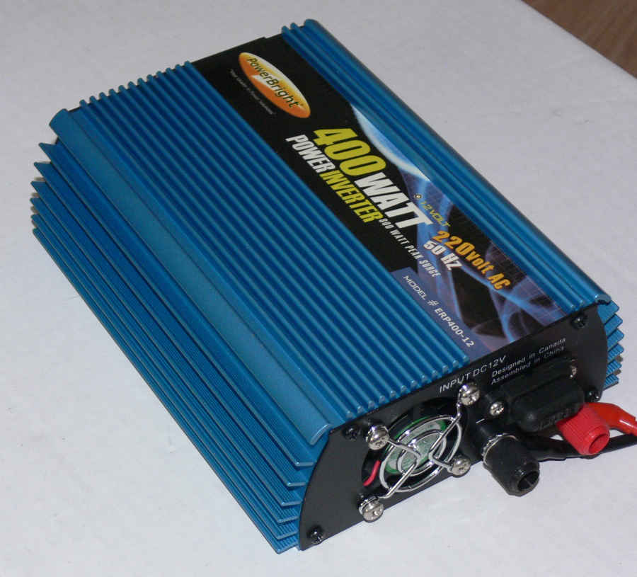
I have a 400 watt 12 volt to 220 volt AC converter waiting
in the wings :)
Kind of old tech because of the 50 Hertz. Heavy and large
but cheap.
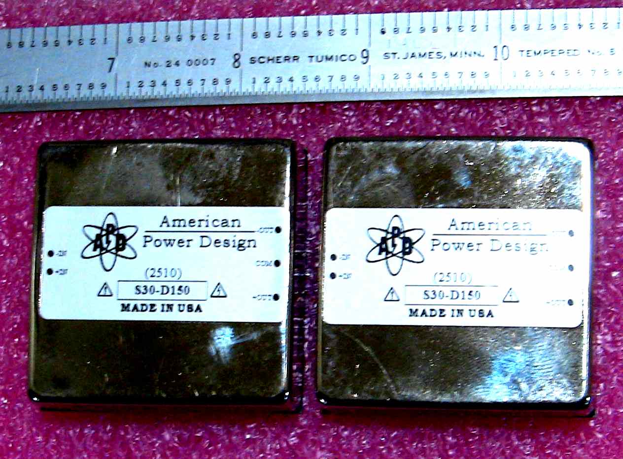
My new 300 volt 30 watt power supplies are
converting at 120 Khz (120,000 cps).
Paul Lamar
--
The Rotary Engine NewsLetter. Powered by Linux.
ACRE NL web site.
http://www.rotaryeng.net
Youtube key word PaulLamar2
Copyright 1998-2010 All world wide rights reserved.