I got the system up and running with the L6388.
Works like a charm.
I never quite understood
why the Aussies were claiming a minimum of two
sparks at high RPM until I looked at the signal
across the 2.5 ohm resister in series with the 1 uF
cap. This resister is simulating the coil,
for now, in the low voltage (12V) test set up.
With 12 volts I am getting a peak current
of .4 AMPS!! through that resistor when the lower
FET turns on and ANOTHER .4 AMPS!! when it turns
off. This is due to the totem pole configuration
of the FET switches. Most CD system use only one
switch.
Imagine what the current would be with 300
volts. Of course the inductance of the coil
will make a difference.
In this set up these two current pulses are 20 usec
apart. The pulse width and timing are controlled
by the ZBasic computer with a simple BASIC
program. RPM is about 9500. The final version
of course will be stand alone with no
computer needed.
Here is a scope picture. The upper
trace shows what the upper FET switch's
input trigger is doing and the lower trace
is the +/- 10 volts across the 2.5 ohm
resister. E = I x R and I = E/R.
In other words when the lower FET
turns on the current pulse in the coil flows
one way and when the lower FET turns off
the current in the coil flows the other way.
Duh!
This means we will have a total of 8 ignition
sparks for each leading spark plug. Groups
of two 10 degrees apart from 22 deg. BTDC
to 10 deg. ATDC. Up to 11,000 RPM or more.
Next step is get the high voltage power
supply and the stock Mazda 2nd gen coil
working. I'll be very surprised and disappointed
if this system does not significantly improve
the BSFC of the rotary.
Hello Paul;
This looks like a nice design. Relatively simple and I
like the pulse pair with each trigger. Even closely
spaced pulses should increase your probability of getting
a good burn started vs a single spark.
But be careful when you choose the 300V supply. Some
quick calculations based on the energy stored/dissipated
in the 1uf capacitor shows that 90mJoules is consumed for
each pulse pair produced. ( energy, in Joules, stored in
a capacitor is CxVxV/2 ) Each of the two pulse pairs
uses the same energy.
At 10k Rev/minute that translates to:
10k/60 pulses/second x 9E-2 Joules/pulse= 15 Joules/second or 15 Watts.
That's for one pulse pair per shaft revolution for one spark plug.
Multiple by the total number of pulse pairs (you always get a pair)
you will use per shaft rotation to get the total DC power
you will need at 300V.
Could be a significant amount of power.
Craig Taylor
I have a 400 watt 12 volt to 220 volt AC converter waiting
in the wings :)
Kind of old tech because of the 50 Hertz. Heavy and large
but cheap.
My new 300 volt 30 watt power supplies are
converting at 120 Khz (120,000 cps).
---------------------------------------------
I did away with the computer and used the actual
hardware to control the L6388. The pulse width
is now controlled by the LMC555. One of the neat
things about this chip is it will not allow
both switches to be on at the same time (disaster) so
that eases the timing requirements. The doc is
not great but fooling around with it will teach
you how it works. I already blew the top
off one but they are cheap :)
I connected a 2nd gen RX7 coil just to see what
would happen. It looks like it wants a 1 ms wide
pulse but that may not be necessary or desirable.
That allowed the coil oscillations to damp
down after several oscillations. See the
attached scope picture. Of course it is still
running on 12 Volts but the time constants
should be the same. This will vary of course
and some coils will oscillate faster than others.
I'll dig up some other coils and try them out.
If you have any old coils lying around you
don't need please send them to me.
About the max we can do with this coil is 8 msec
(7500 RPM) /36 or 222 usec if my math is correct.
2.2 to 10 to the -4 or 0.000222222... 222 usec
I think. We will probably get one or two oscillations
going down and the same going back up.
Next step is the 300 volt power. I'll use
the 400 watt inverter as I don't want to risk the
expensive power supplies just yet.
BTW for dyno test I don't need the inverter.
It will be possible to merely plug this
ignition system into the 220 volt wall outlet
found in the shop :)
Paul Lamar
Paul, I recall there being a "low inductance" ignition
coil designed for CD ignition systems. With the standard
Kettering system, the energy to produce the spark is stored
in the inductance of the coil, which makes a substantial
amount of coil inductance desirable. With the CD system,
the energy is stored elsewhere and too much inductance can
be a problem, as you are discovering.
Craig Taylor
Yes I think you are right. Probably the best bet
is a MSD coil designed for CD systems.
BTW I just noticed that Klaus (or Paul Lipps the designer) is
using three Hall Effect sensors spaced 1/4 inch apart. Could he be
using the same idea? :) In case somebody accuses me of copying
Klaus's system I did not know about this until yesterday when
I noticed it on his web site.
http://www.lightspeedengineering.com/Products/MiniSensor.htm
"Single systems require only one Mini Sensor. On dual 4 cylinder
engine installations, there are two Mini Sensors at 180 degree
intervals. On dual 6 cylinder installations, a second Mini Sensor
is mounted 120 degrees from the first."
"The Mini Sensor consists of two billet aluminum machined halves
that capture a small circuit board holding 3 Hall effect sensors
at 0.250? spacing."
End quote. I don't know what KLaus is using for coils but
they appear to be off the shelf. Looks can be deceiving:)
I have seen it many times but I never paid any attention.
Klaus's excellent results indicates this idea will
also improve the BSFC of the rotary.
BTW Craig the output of my 220 volt bridge rectifier looks
like this.
220V____ ________ _______
| | | |
0V |__| |__|
Do you think I have a bad diode in that bridge?
Paul Lamar
Paul,
Yes, I see what they are doing with the three hall effect sensors and the
groups of 4 magnets buried in the flywheel at 120* intervals (or 180* for
4-cyl apps). It is important to see that each of the groups of magnets
are
located on a different radius. Each group of magnets aligns with one of
the
three hall effect sensors. That looks like a good solution for a 3-rotor.
By separating the hall effect sensors by .0250", it solves the problem of
distributing the spark to the corresponding rotors at the proper time. It
seems that the LSE would almost have to utilize a separate ignition
circuit
for each hall effect sensor. This would allow the circuits additional
time
to recharge before the next firing event. As I understand it, the LSE
treats a 3-rotor like three one-rotor engines tied together with a common
eccentric shaft.
Mark
A three rotor is equivalent to a six cylinder when it comes
to sparks per rev. The LSE might work on a rotary but I don't
thing so. The design for the rotary is more difficult due to
the much higher RPM. He has a much easier time of it as the AC
piston engines run one third as fast as the rotary.
Do you know somebody running a LSE on a rotary? I'll ask Klaus
when I see him again if he has sold any to Rotarians. I think I
would have heard about it from Klaus.
Paul Lamar
Paul,
No, I don't know of any rotaries running the LSE ignition. But, if I'm
correct in assuming the 6-cyl model uses three separate ignition modules (I
could be wrong), then for a 20b running at 6000 rpm, sparks/minute would be
like a 4-cyl recip running at 3000 rpm (for each module). Piece of cake
for
one spark per, but if he's firing each combustion event 4 times in rapid
succession, that is another situation altogether.
Mark
I think the 4 -cyl equivalent is 4000 RPM. Klaus may run his engine
at 3000 RPM. We must get this working at 11,000 RPM because a lot
of rotary racers run there. I think he is firing at least 3 times
and maybe six times in rapid succession if he has caught on to the
Aussie totem pole configuration. Klaus used to tell me it was firing
continuously but I never got Paul Lipps to reveal how he was doing
that. I at first thought he was using a crt flyback transformer. I
think that is why Klaus calls it the Plasma ignition system :)
Paul Lamar
Paul,
I was most impressed with the LSE trigger design. Simple & elegant.
Mark
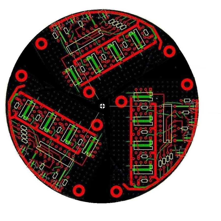
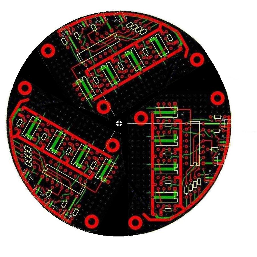
Thanks Mark. I was almost able to get everything on the
trigger board except the 1 uF 300 volts caps. Perhaps I can do
that if I go up on the diameter from 4 inches to 6 inches :)
I am sure it would be possible if I switched to surface mount
components.
One idea I had was to put fins on the magnet wheel to act
as a fan to cool the electronic components.
Patent applied for.
Paul Lamar
--
The Rotary Engine NewsLetter. Powered by Linux.
ACRE NL web site.
http://www.rotaryeng.net
Youtube key word PaulLamar2
Copyright 1998-2010 All world wide rights reserved.