Paul,
I flew my p-port 3-rotor Lancair ES on Friday. OAT was about 90*F, but
coolant stayed below 200 during climb and oil temps were 185*F max. The
p-port engine ran great, except for a little mis-firing around 5700 rpm,
which was corrected in flight with auto-tune. Pre-takeoff run-up gave a
brief excursion to 6900 rpm. Takeoff run was 6500, running very well, but
limited by prop setting. It started to misfire when I dialed the prop back
for cruise-climb, so I cranked it back up to 2000 (prop) and it ran smooth
again. Once at 3500 and leveled off, I entered auto-tune and brought the
rpm down to the 5700 range and let the EM-2 tune the EC-2, map addresses 90
- 92. Afterwards, it ran great throughout the rpm range. (I had
"auto-tuned" much of the upper map range on the previous flight.)
At 3500 - 4500 MSL, the EFIS was indicating 172-174 TAS at 1800 rpm prop
setting, and 201-203 mph per the EM-2. This is consistent with a previous
test run I had recently done and represents a 12-14 knot improvement over
the side-port motor. The cool thing is that these speeds are in "economy
cruise" mode. Engine was just purring along at 5500 rpm. There should be
a
bit more speed on the table as I realized after the flight that I had never
closed the cowl flap. ;-)
Later on, I will run it a bit harder, around 6500 rpm, and see how she
performs. But the vast majority of my flights are in the 5200 - 5500 rpm
range. So, this is very good news.
Mark
Yes it is Mark and you are now the current chief P-port pioneer
replacing Everett Hatch and Steve Beckham of old Power Sport.
Also the first person to fly a P-port 3 rotor I suspect. You
are also the first person to successful fly a slide throttle
as well. (I don't count crashing the airplane on landing a
successful flight :))
Congratulations. I suspect Tracy's EFI system is being put to the
test. It is one thing to get it to work with a fixed pitch prop and
quite another to get it to work with a variable load, constant
speed prop. I suspect it could use a bit more sophisticated
power monitoring system than just a MAP and air temperature
sensor. Perhaps a MASS air flow sensor would make it easier.
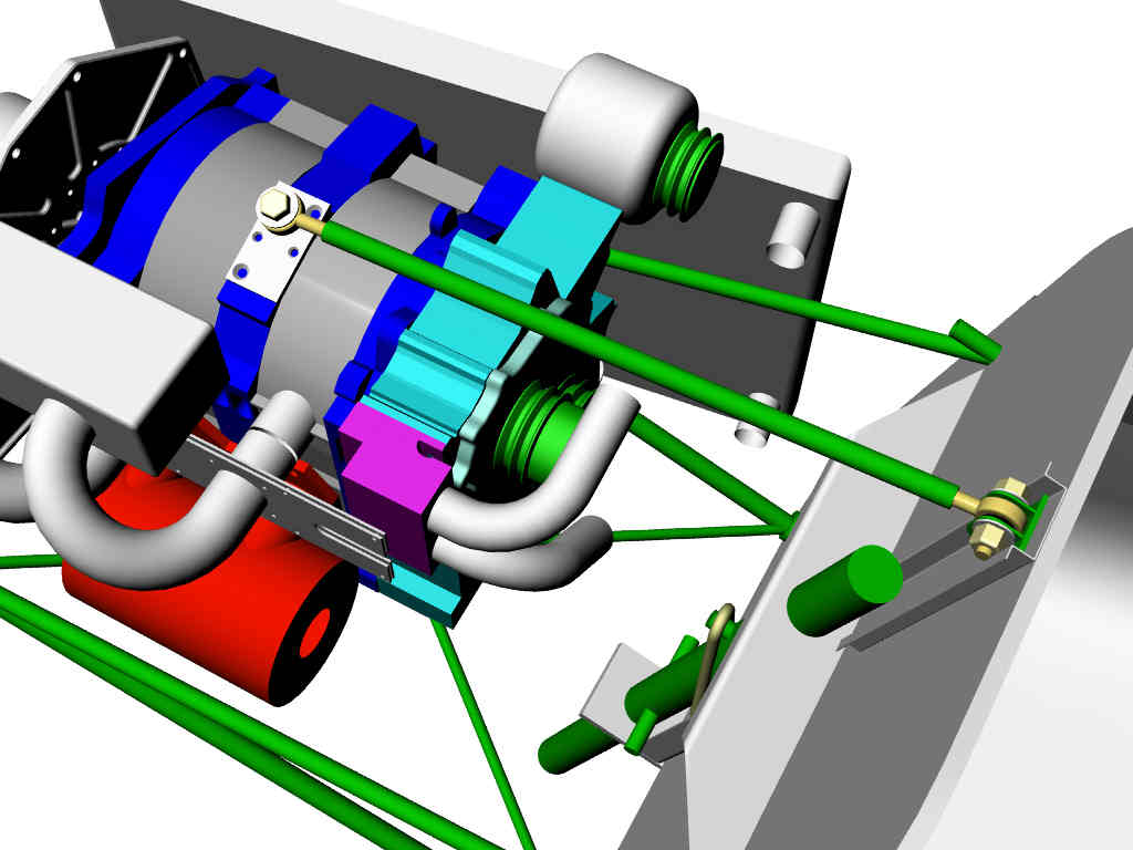
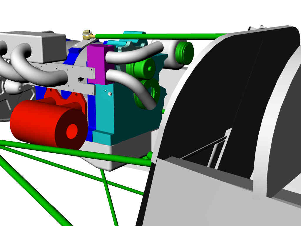
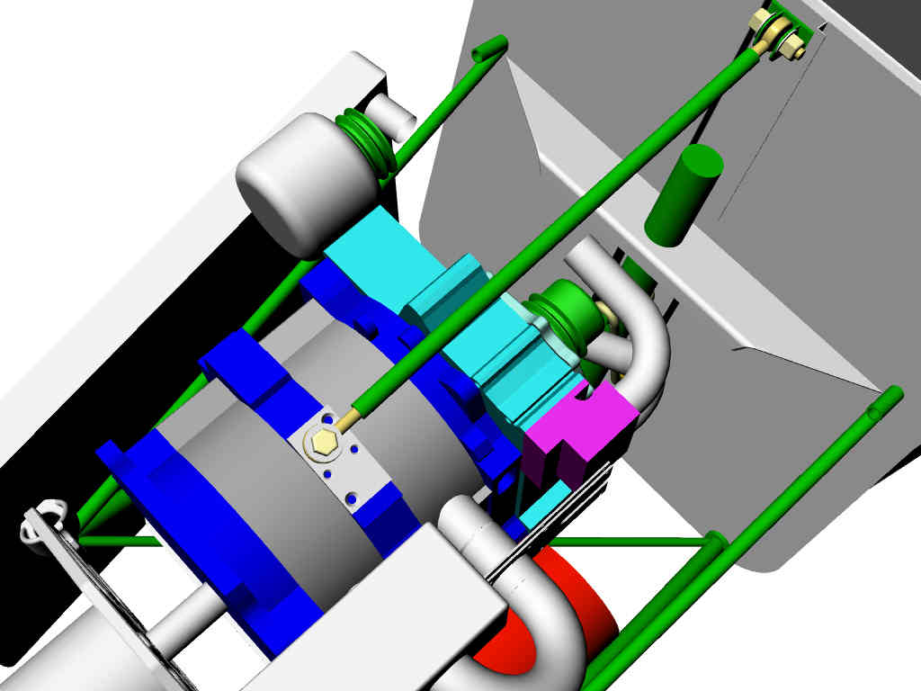
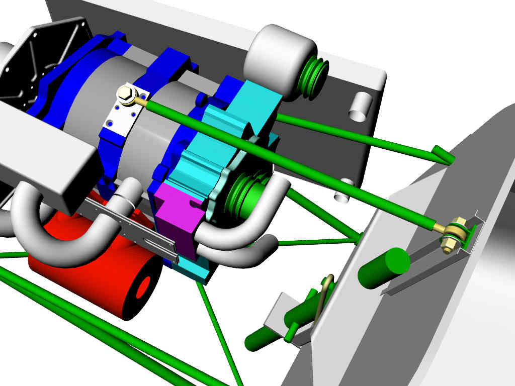
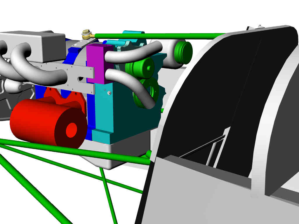
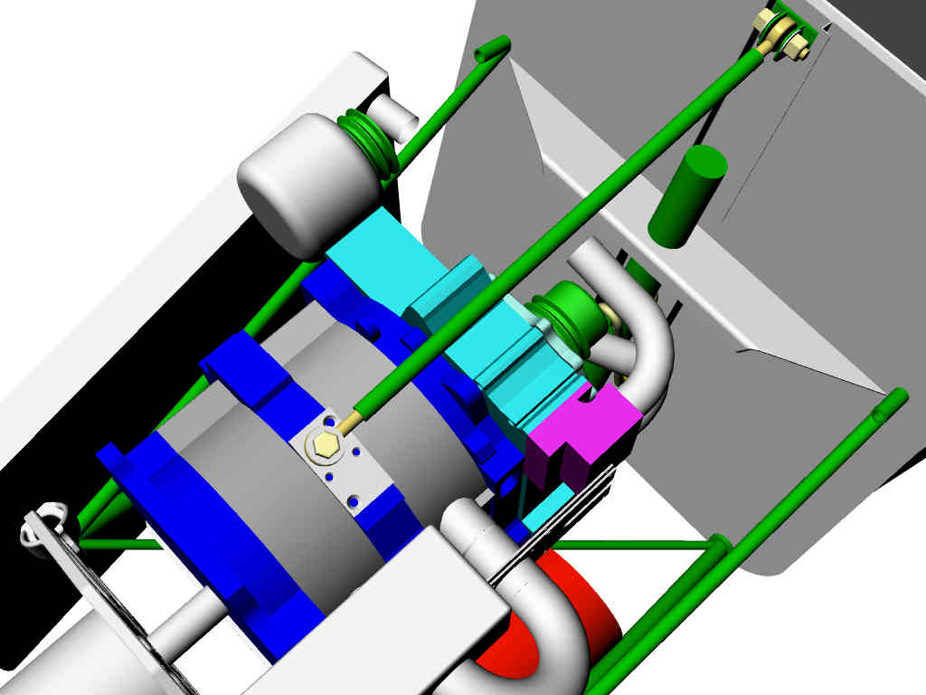
I need some pictures of your cowl flaps and the new cooling
system.
Paul Lamar
Paul,
Yes, I agree there's a need for a more sophisticated ECU, but with so few
builders using a C/$ prop, I'm not holding my breath. Maybe a Megasquirt is
in my future.
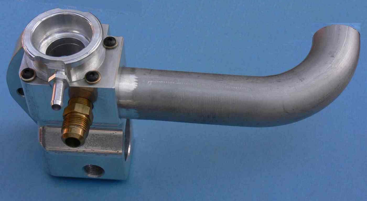
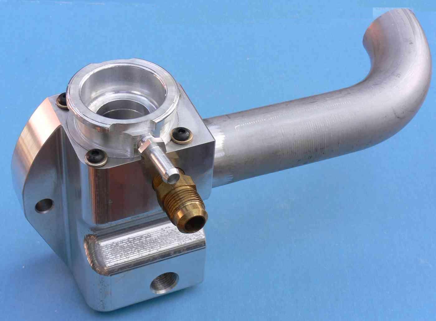
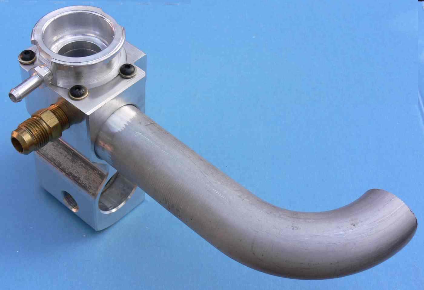
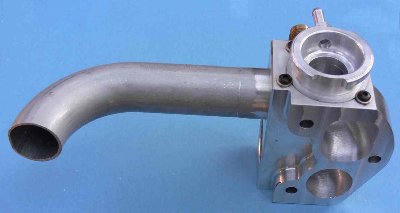
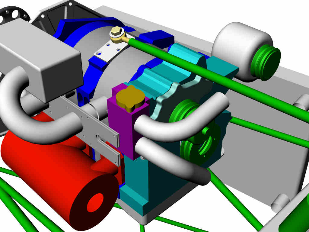
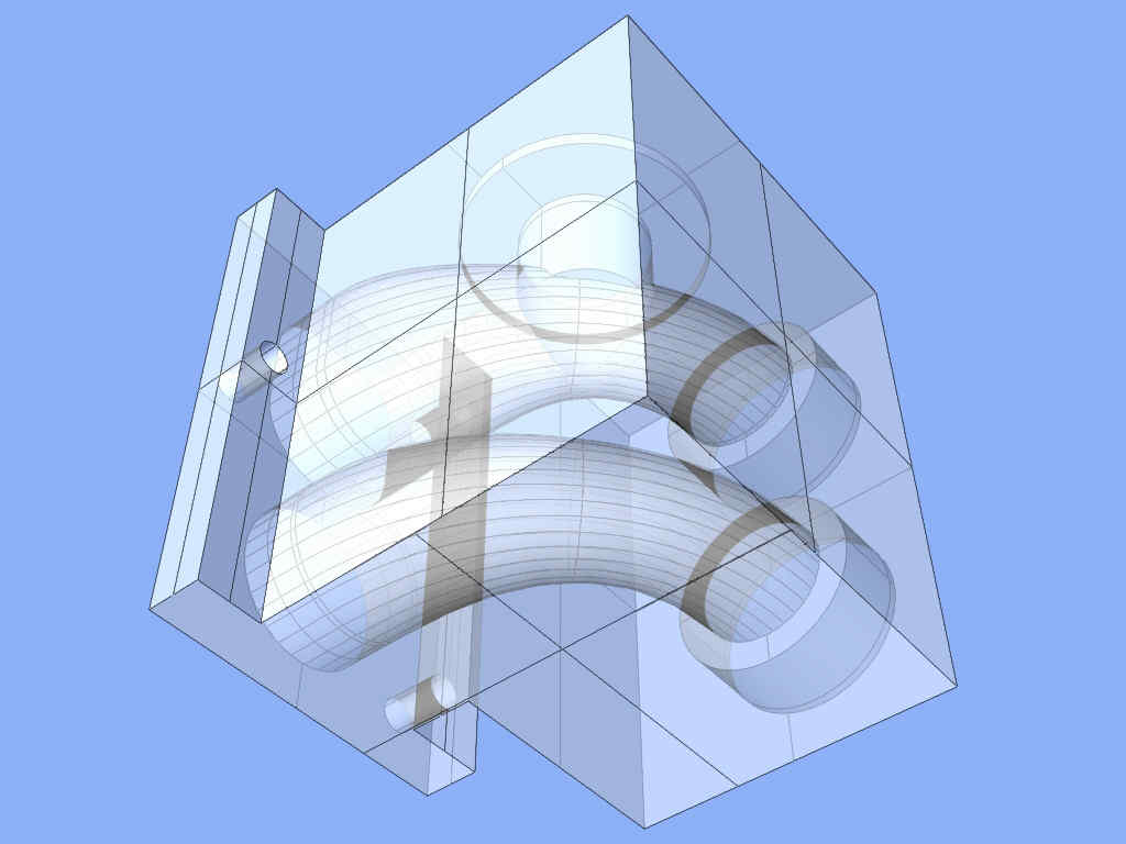
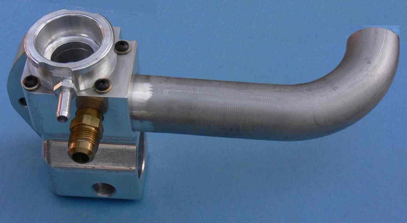
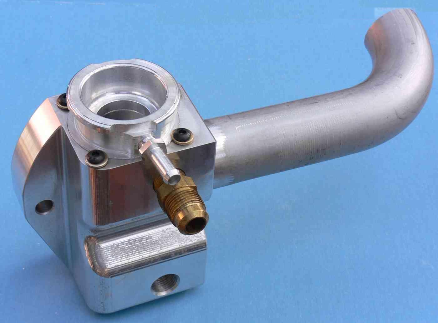
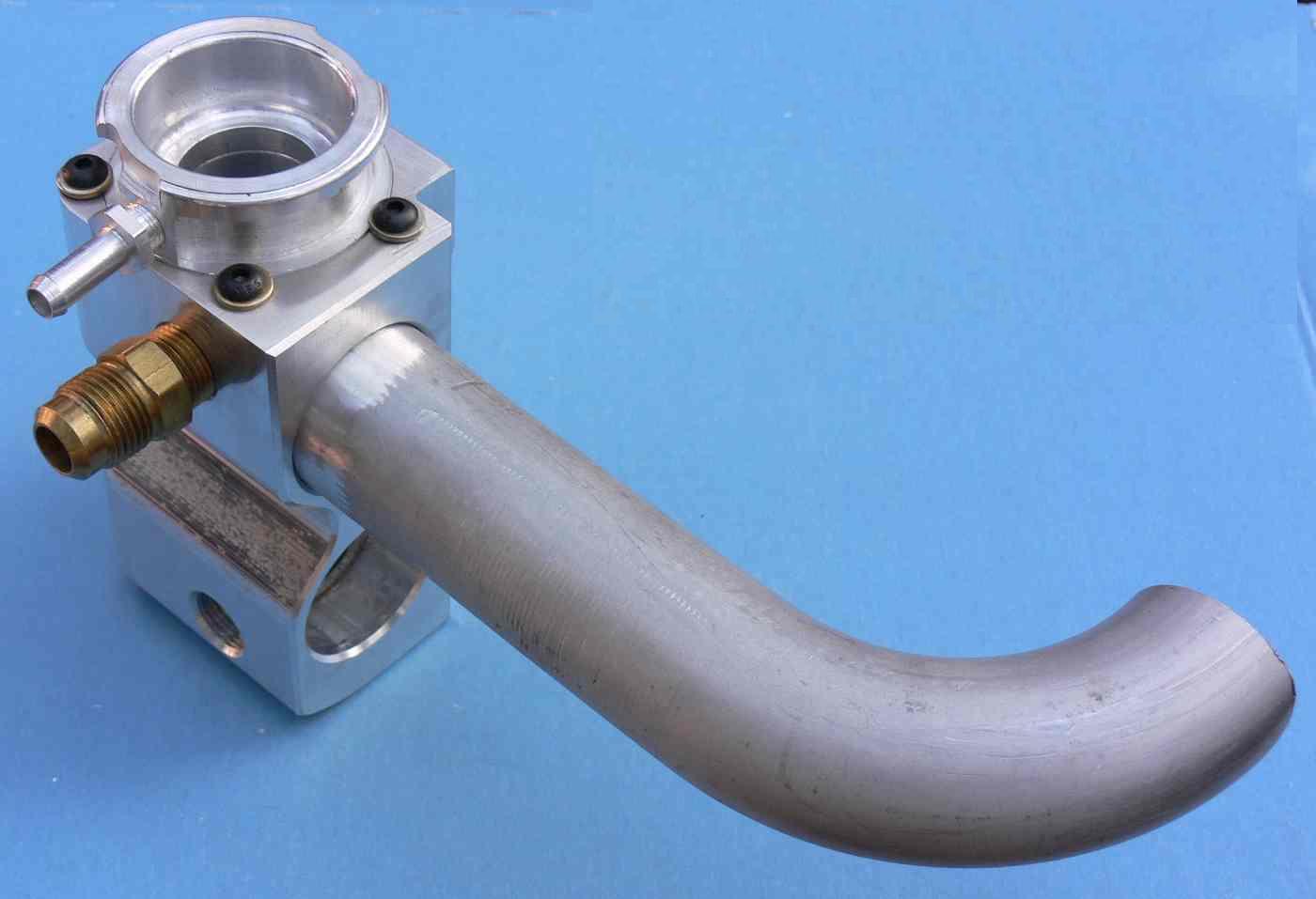
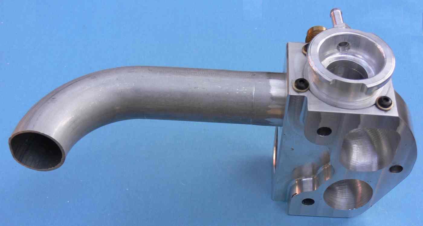
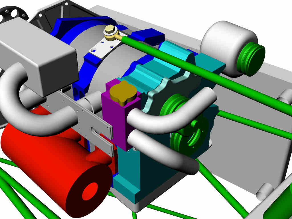
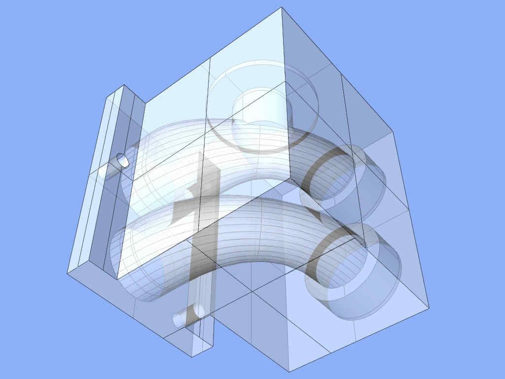
I have one suggestion on the Renesis WP adapter block. It would sure be
nice if it incorporated the wiggins couplings so you don't have to weld them
on. The inlet/outlet are very close together so it is difficult to get the
tig torch in position to weld them. I've got a small leak in that area that
I will try to fix by applying JB Weld from the inside. I also had trouble
getting the adapter to seal against the Renesis WP without leaking. I ended
up installing a Mazda metal gasket which did the trick. I guess that's why
Mazda uses a metal gasket in that location. I'll send some pics later.
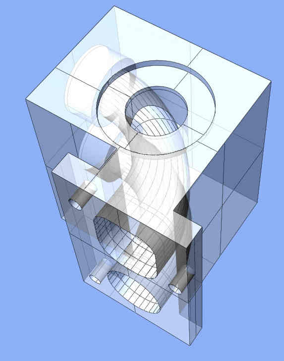
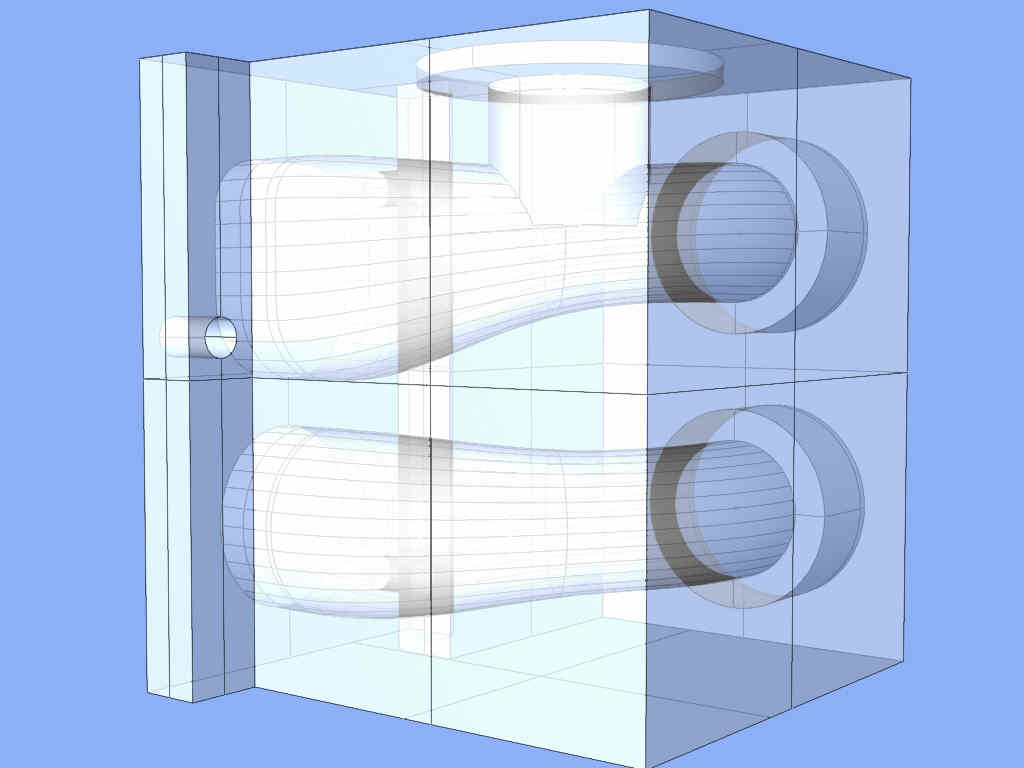
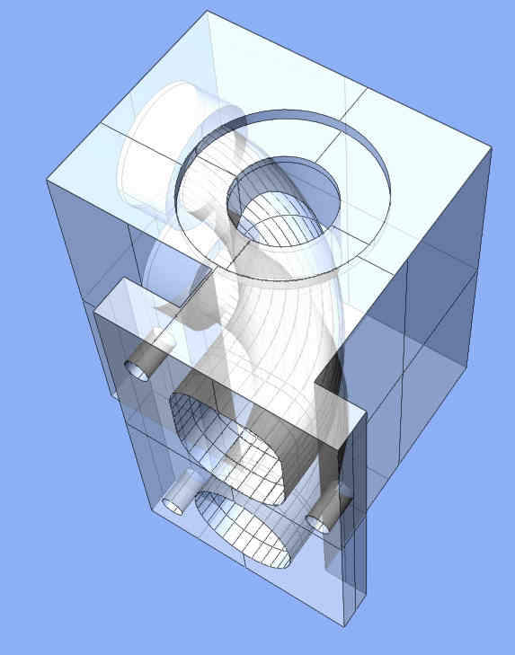
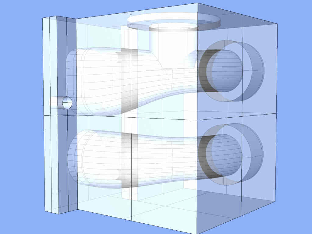
I just had an idea for the Renesis WP adapter. Since everyone's design
dosn't facilitate a rear inlet/outlet, could they be built with the passages
in the casting, but not drilled all the way through the block. This would
allow the builder to choose either a rear, side, or bottom inlet/outlet, or
a combination of any two. A low cost hole cutter in a drill press would do
the job. Just a thought. (patent-pending)
Mark
Hang on my ZBasic system is coming along fine. The RPM module was
the most difficult to do. The rest are easy such as the
firing the injectors and reading the EGTs.
You will need a mass air flow sensor with out the throttle
part so think about where that will go. I don't think the
megasquirt will work without a throttle position sensor
and O2 feed back.
Jeff can think about that as he is now building both.
He would probably have to thread the wiggins into the block.
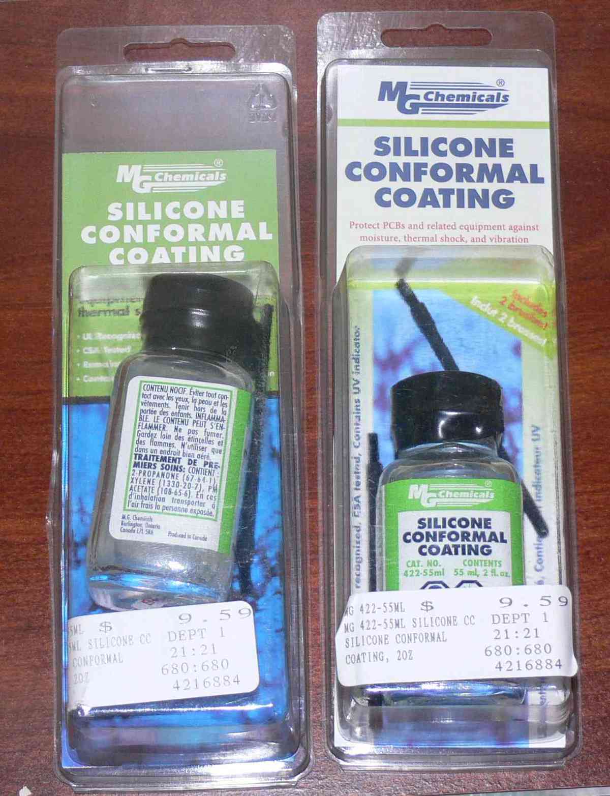
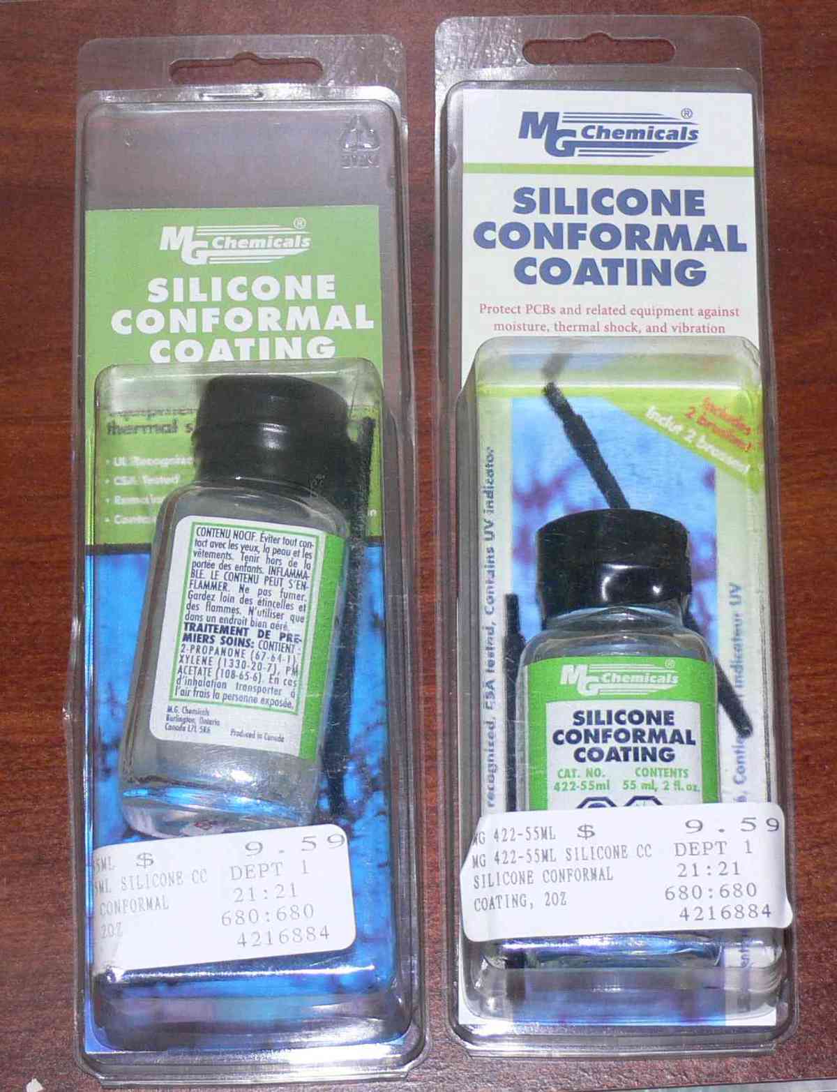
Use silicone conformal coating instead of JB weld as the
viscosity is much lower and should wick into the leak.
You can apply it with a que tip from the inside and
apply air pressure so it flows into the leak.
I really intended to screw something in there on
the first iteration but later decided to bond
a tube bend or two in with JB Weld but that requires
careful chemical prep of the aluminum parts.
Perhaps Jeff can machine an internal O-ring groove in
the block and mechanically attach the wiggins or a tube
bend with welded on clips and screws.
Paul Lamar
--
The Rotary Engine NewsLetter. Powered by Linux.
ACRE NL web site.
http://www.rotaryeng.net
Youtube key word PaulLamar2
Copyright 1998-2010 All world wide rights reserved.