I was developing the RPM counter module to be stable
over a wide temperature range using a a hair dryer and
was blown away by the CMOS 555 chip yet again. (Yes jd?)
This is an amazing chip. It will work over a wide
range of combinations of resistance and capacitance.
I needed it to oscillate at 26.66 cycles per second (Hertz for
the young guys.) when divided by 16 that gives a frequency
of 1.66 CPS or a measuring period of .6 seconds. I had
a spare divide by 16 counter left over on the PC board.
Assume there are 100 teeth on
the flywheel. At 7500 RPM that is 125 RPS times
100 teeth or 12,500 CPS. If I count that for .6 seconds
I get a direct read out of 7500 RPM.
Back in the old days before the CMOS 555 (BCMOS-555) that was
a tall order. Not only that but that oscillator frequency must
not vary significantly with temperature or the RPM
will not read out correctly.
Here is the capacitance verses temperature chart for a
typical ceramic capacitor. Note the rapid change
in capacitance with temperature. Fortunately there
is a type of ceramic capacitor that is more stable
called a COG-NPO. That is what I am going to use.
Unfortunately they do not come in capacitance greater
than .001 ufd. Now the problem is getting the 555 to
oscillate at a super low frequency with such small
capacitance. The .001 cap is right down near the bottom
of the R-C-verses frequency chart so I will use
two COG-NPO .001 caps in parallel giving me .002
ufd to work with.
CMOS 555 to the rescue. Here is the chart
for the 555. One needs about a 10 meg resistor along
with the .002 cap to get the correct frequency.
Usually a crystal oscillator is used but the common
crystal oscillators oscillate around 32,000 CPS.
That requires a very long counter chain to act
as a divider. This can be done with a signal chip
computer of course but there are all sorts of drawbacks
to that. I want to keep this simple so anybody can build
it without a Phd in assembly language programming.
I have been there and done that.
See
http://www.rotaryeng.net/EEE-road-test-sys.pdf
I have been accused of being stupid for attempting
this and not using a single chip computer so let me
know if you see something stupid.
Paul Lamar
Nothing stupid. A possible improvement.
The use of very high impedance circuits in aircraft can be troublesome,
as they become very sensitive to noise and interference from other
electrical activity. A 10 meg resistor can act as a variable resistor in
the presence of magnetic fields, such as from an alternator wire. For 39
cents Newark will provide a M74HC4040B1R military-grade 12-stage binary
divider.All it needs is 5 volts, ground, your 555 timer for an input,
and pick any of the 12 outputs for your clock. You can then drop the 10
meg resistor down to 10K and use the Q10 (divide by 1024) output of the
divider for your .6 second clock.
This will dramatically reduce the need for both electrostatic and
electromagnetic shielding.
Victor Roberts
Thanks for looking at this Victor. Unfortunately I don't
have room on the board for it. If I make the board larger it doubles
the price. I only needed 3 out of the four 16 bit
counters so I used the unneeded one as 16 bit divider. That helped.
I also found a .0022 COG-NPO and I have room for three of those so
that should drop the 10 meg resistor way down. There is also a .01
ufd COG-NPO for five times the money which I also have room for. That
will drop the resistor down to about 1 meg.
I'll take your advice and use that to lower the impedance. I will
also tell people to keep the entire computer away from the alternator
wire as there are a lot of high impedance circuits in the computer.
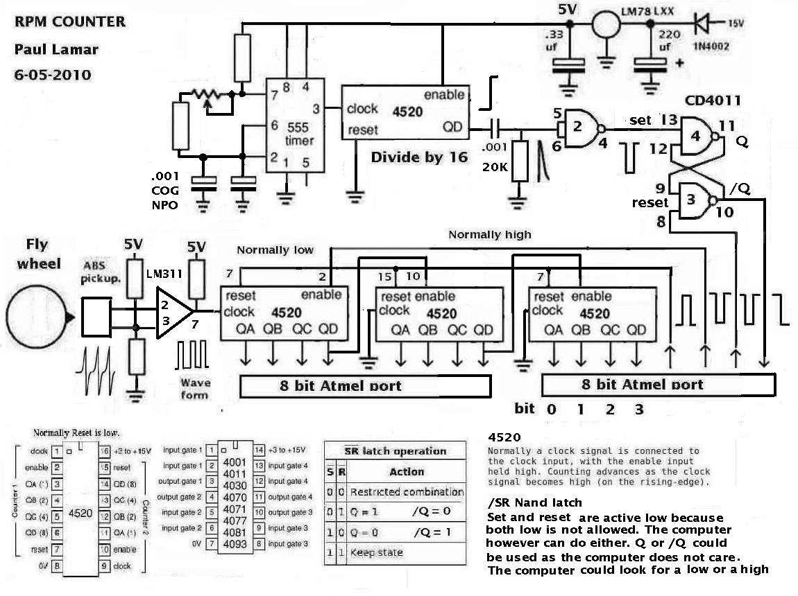
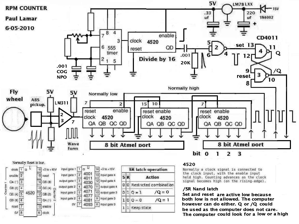
Here is the latest schematic using the LM311 mag sensor comparator.
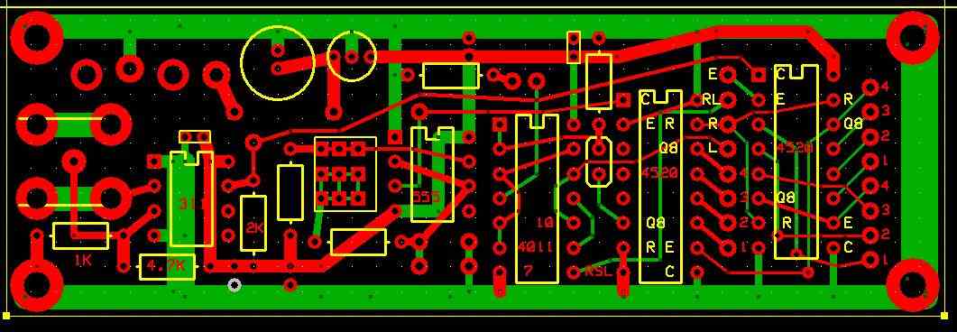
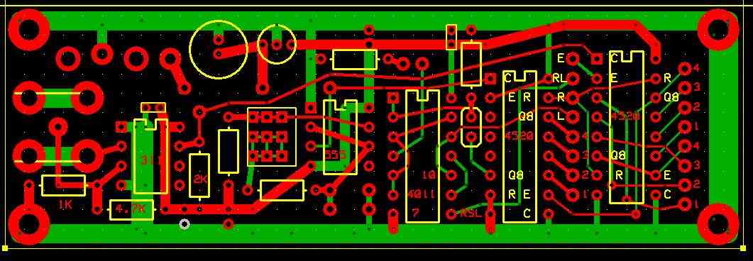
Also the latest circuit board. The COG-NPO cap goes just below the 555.
I have a large stock of 1/4 watt resistors but I should look into
buying some 1/8 watt. That will save a lot of space.
I don't want to go surface mount as I am getting too old
to solder that :) and it is much tougher to repair or change.
I also have a large stock of dips and high quality machined
pin sockets. I have some CMOS CD4040's as well.
Paul Lamar
--
The Rotary Engine NewsLetter. Powered by Linux.
ACRE NL web site.
http://www.rotaryeng.net
Youtube key word PaulLamar2
Copyright 1998-2010 All world wide rights reserved.