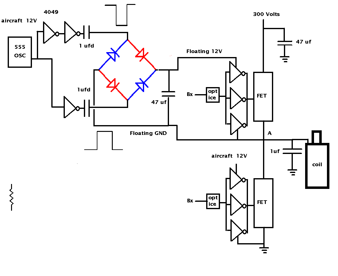
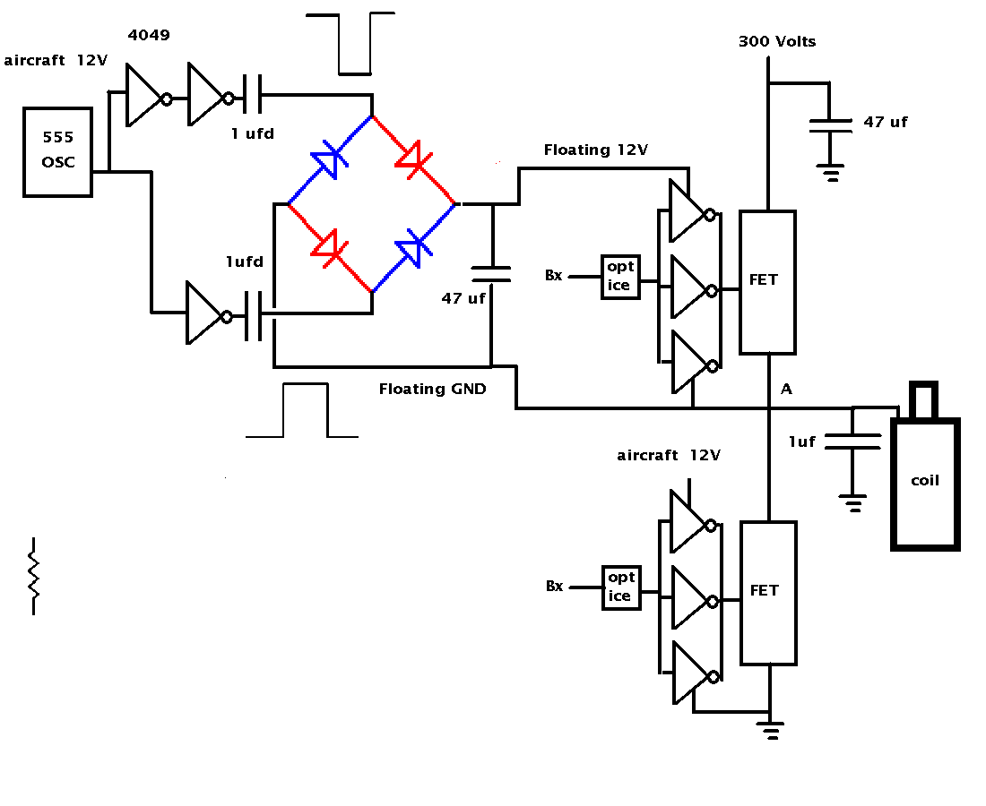
It is called a high side switch and it is used
to isolate the 300 supply when the 1 mfd cap
discharges through the coil.
The single chip half bridge drivers that are supposed
to do this are not designed for a cap discharge ignition
system that must run from a dozen rotations of the engine
when it is starting to 7500 RPM or 125 PPS.
Also the cap discharge ignition system duty cycle
must deal with pulses only a few hundred micro seconds
wide in a period of 8 milliseconds. Most high side
switch chips expect a 50% duty cycle.
This may look simple as frequently good ideas do
but this doubles the voltage available for firing
the high side FET. Works so well I was surprised.
It relies heavily on opto isolators
and CMOS CD4049's which are 50 cent chips.
Six to a package so that makes each amp less
than 10 cents.
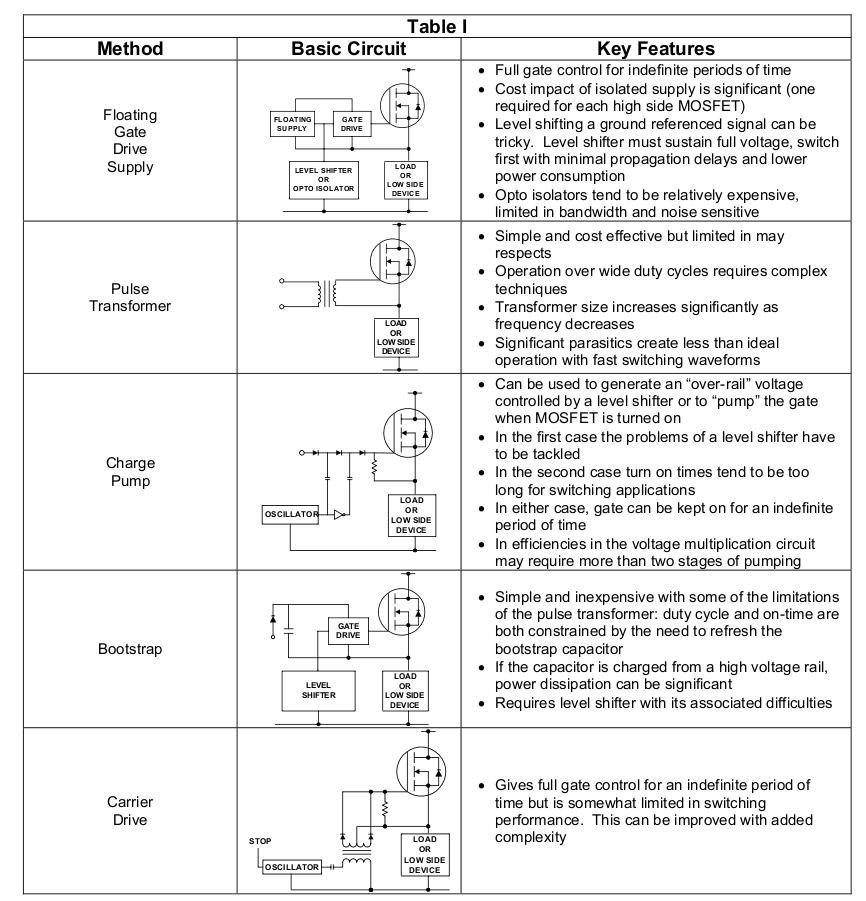
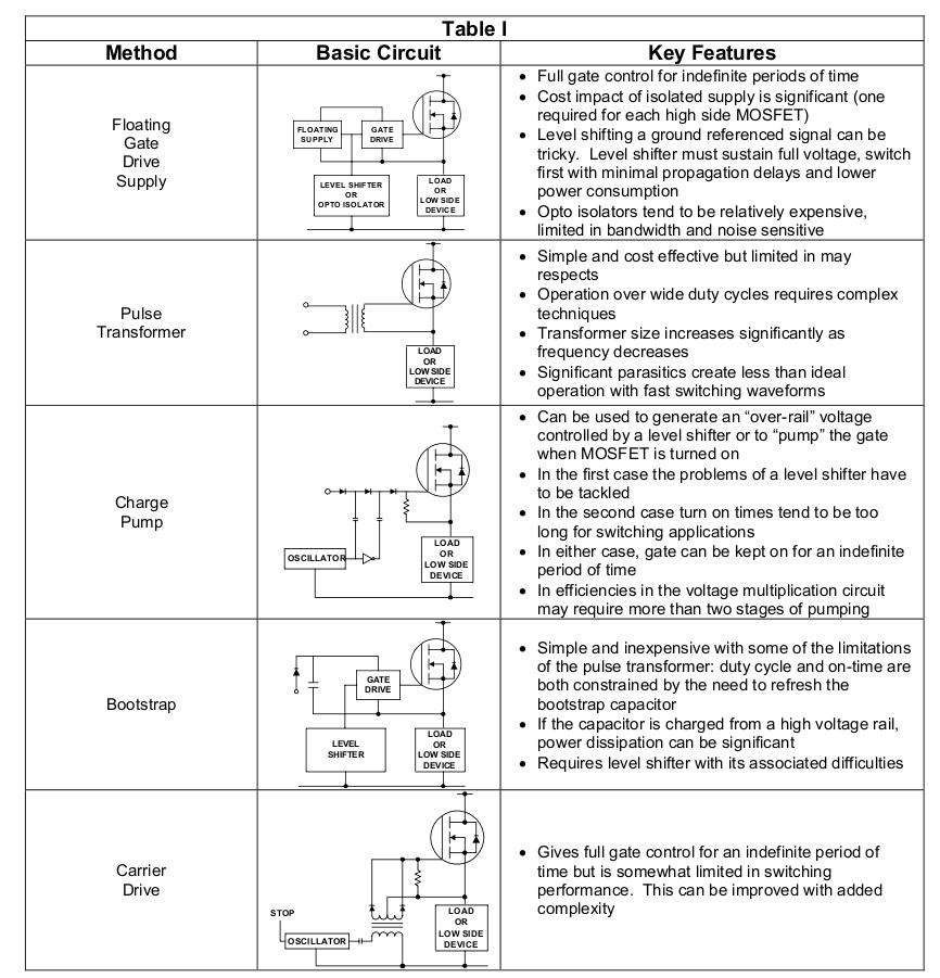
Here is the schematic and a table of traditional
approaches to this problem. Note; this trick is
not in the table :)
It took me a half hour to mock it up and test it
once I had the idea.
I'll be using a cheap ATmel single chip computer
to handling the timing of turning off the PS and
discharging the cap. It is easier to do that
than provide the necessary delay with logic gates.
The Atmel chip is programmed in ZBasic just
like the main computer.
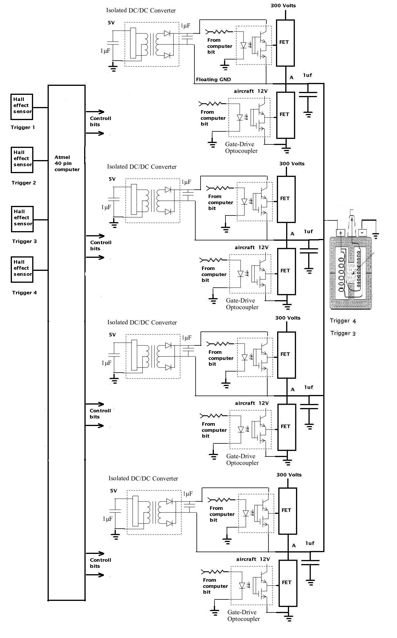
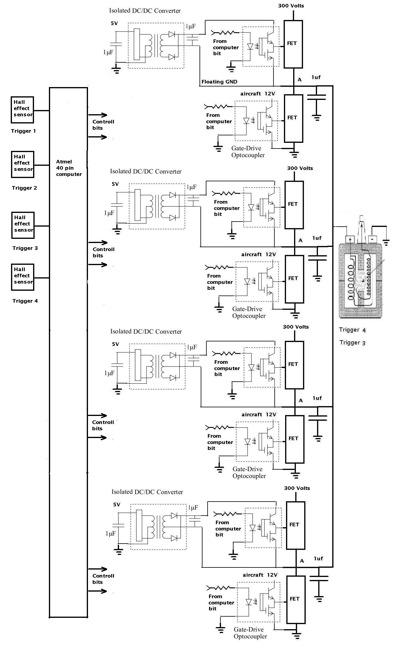
The schematic is one of four identical circuits for each
leading plug. The leading plugs will fire four times, 10 degrees
apart, of e-shaft rotation. The trailing plug will use
some other entirely different ignition system
as a safety feature. This is a highly redundant system.
If one of the these circuits fail you may not
notice the difference except for a slight increase in
fuel burn.
-----------------------------------------------------
After I designed and tested this I discovered a single chip
device from Burr Brown and TI that does more or less the same thing.
These cut the component count way down at the expense
of more cost.
There are now a total of 8 CD strikes in groups of 2 every
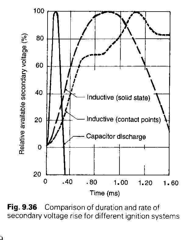
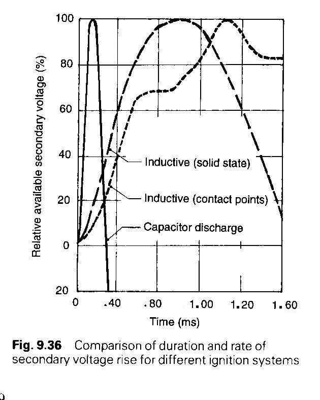
ten degrees starting at around 22 degrees BTDC. The 1 ufd
capacitors have plenty of time to recharge up to 10,000 RPM.
The goal here is a significant reduction in BSFC for
the rotary.
----------------------------------------------------
Here is the Atmel single chip super simple ZBasic
test program that fires the plugs with the correct timing.
==================================================
public x as long '0 to about 100 million
public y as byte '0 to 254
public z as long '0 to about 100 million
Sub Main()
Register.TIMSK2 = 0 'turn off Real Time Clock
'interrupts the main program and causes spark
'timing jitter if left on.
for x = 1 to 500000000
Call PutPin(89, ZXOutputHigh) 'top FET turn PS off
for y = 1 to 1 '10 usec delay
next y
Call PutPin(88, ZXOutputHigh) 'bottom FET fire the cap
for y = 1 to 200 '80 usec delay
next y
Call PutPin(88, ZXOutputLow) 'bottom FET turn cap off
for y = 1 to 1 '10 usec delay
next y
Call PutPin(89, ZXOutputlow) 'top FET recharge the cap
for z = 1 to 500 '1/2 millisecond 60,000 RPM
next z 'delay
next x
End Sub
==========================================================
This is the "z" timing for two sparks
for one or two rotors. It is highly modular
so it can be used for one, two, three or
four rotors just by adding sections.
8 msec = 7500 RPM one coil 1 plug
4 msec = 7500 RPM waste spark coil fires 2 plugs.
Rotor one and rotor two leading plugs.
4 msec = 15,000 RPM one coil 1 plug
2 msec = 15,000 RPM waste spark coil fires 2 plugs.
Rotor one and rotor two leading plugs.
In theory then this test program will
work up to 60,000 RPM with the current test z timing.
More than enough :)
The 1 ufd capacitor is on for only 80 usec so that time
still needs to be experimentally determined. I have tested
it with another program at 100 usec which seems to work.
It could go as high as 400 usec.
Much depends on the actual coil inductance. I have a 2nd
gen waste spark coil that I will be focused on developing
for.
This is actually two sparks. One when the cap is turned
(lower pulse) on and one when the cap is turned off.
This system is so simple and so easy do do I have decided
to add two 2nd gen single coils for the trailing plugs and
fire them once at 22 degrees BTC. Therefor this will
be a complete retrofit-able ignition system for
2nd gen Mazda RX7s. The trigger wheel will change
and the CAS replaced by Hall Effect sensors.
The trailing plugs will fire 8 times over 40 degrees
of e-shaft rotation and the leading plugs only twice
at 22 degrees before top dead center. Lot of flexibility
here so all sorts of splits and advance/retard are
possible.
Paul Lamar
--
The Rotary Engine NewsLetter. Powered by Linux.
ACRE NL web site.
http://www.rotaryeng.net
Youtube key word PaulLamar2
Copyright 1998-2010 All world wide rights reserved.