Can you lay out a simple schematic of the ADIS-4 firing two
separate coils? One for the front rotor and one for the rear
rotor. I was thinking the ADIS-4 #10 pin fired one coil and the
front rotor and the #12 pin firing the other coil for the rear
rotor, I am confused by the 12 volt power supply wire, through
the #8 pin, going directly to the dual coils. I am using a
separate ADIS for the trailing plugs and all four coils that
came with the Renesis engine so I won't have a wasted spark.
--
Karibian
A 4 cyl EDIS won't work IMHO.
It uses two waste spark coil packs to handle four spark plugs.
Using a waste spark on the trailing plugs is not allowed
so you are one coil short.
An 8 cylinder EDIS system on the other hand uses four waste spark
coil packs (four single coils) So you can use two stand alone coils
for the the trailing plugs and one waste coil pack for the leading
plugs I think but I would check it on a bench test set up before I
put it on a rotary engine. It is also possible to use four stand
alone coils with the 8 cylinder version which is what I recommend.
Which EDIS system do you have? You will also have to find
a Ford EDIS trigger wheel.
http://www.megamanual.com/ms2/36-1.htm
This pdf covers the whole thing for a piston engine.
Paul Lamar
Paul, The EDIS 8 fires every 90 degrees of shaft rotation so only half
the
outputs are usable on an engine firing at 180 degree intervals. The
hall
effect sensor is mounted about 52 degees befor the ignition point and if
hooked up to the EEC 4 or 5 computer backs up the timing for advance.
Without an input from an EEC 4 the coils fire 52 degrees of teeth on the
trigger wheel from where the hall effect sensor is mounted.If I
understand Karibian in his post he wants to use two EDIS 4 modules each
firing two plugs at 180 degree intervals. If there are two hall effect
sensors 180 degrees apart around the trigger wheel (18 teeth) each
firing an EDIS module there are four independant sparks at 180
degrees. If the second Hall effect is retarded 1 tooth it will
fire the trailing plugs 10 degrees different than the leading
plugs. Leaving the 18 tooth separation and firing leading and
trailing plugs at the same rotation provides a completely
redundant ignition system. The EDIS is a waste spark system
meaning that the spark energy goes to the cylinder with least
pressure fires that plug goes thru the engine block and fires
the second plug on the circuit back to the coil. If only one
plug is connected to the coil pack a path to complete the
circuit brom the block back to the other terminal on the waste
spark coil must be provided.Firing only one plug will
dramatically increase dwell on the plug. The EDIS and Hall
effect sensor are really light, inexpensive even if new parts
are used so using two of them doesn't seem to be a problem. The
parts are encapsulated in a plastic block so moisture,
vibration, and low air density should not effect their
reliability. Using two 4 cylinder coil packs does add weight
but until someone weighs two of them as compared to four single
plug coils the difference in weight is unknown. Using the 4
tower coil packs that came with the EDIS would match the
electrical resistance and inductance of the EDIS and coilpacks
as Ford designed them and would be expected to be as reliable as
the car ignition. My piece of mind is worth a few ounce weight
penalty using the waste spark coils. The coil pack is actually
only two coils molded together with a tower connection of both
ends of each of the two coils for a total of four plug
connections. Two coilpacks is a total of four coils just like
four individual coils just less mounting brackets to fabricate.
george grimes
I was afraid of something like that. Do you have a chart of
a Ford V8 showing when each cylinder fires as a function of
the crank angle? I have the firing order. Is the Ford a single
plane crank or 90 degree crank? Must be a 90 degree crank if
it fires every 90 degrees. Too bad I thought I was on to something.
I guess you will need two 4 cylinder EDIS. With a little
fooling around I think I can get one CAS to fire two
units. Those are mag sensors and not Hall Effect.
Hall effect require rotating magnets. Ford calls them
"Variable Reluctance".
I would not use the waste spark coil pack on the leading
plugs with just one plug. I am not sure
why. Have you tried it with out a spark plug load?
I dimly remember from way in the past that could be
a no no. Perhaps it arcs over inside the tower.
Paul Lamar
Paul, It fires an EDIS 8 every 90 degrees just like when
it had a distributor cap. It fires one coil pack every 9 teeth
on a 36tooth wheel. Using the waste spark coils fires the 4
cylinders on the second revolution using the same four outputs.
Using a 27 tooth wheel with an EDIS 8 there would be three
outputs 120 degrees apart (still counting 9teeth) and the
missing tooth would reset the count not firing the
fourth output'. I haven't tested this three rotor idea but IMHO
that is how it works based on two weeks of Internet research.
Personally for the return circuit back to the waste spark coilI
suspect a resistor would be required in series with the
plug lead. I am intending to just screw some extra spark plugs
into a block of aluminum bolted to the block which won't fire
anything just provide the electrical load. For the four rotor
there is a small pad on the connector bell housing between the
engine sections thick enough to screw the plugs into which was
necessitated to be able to remove the pattern from the
castings and You are right they are actually variable reluctance
coils not Hall effect. I am going with two of them so that I can
fire the plugs separated by a few degrees of E-shaft rotation and
to make each half of the ignition completely independent. This
is also a multi-spark ignition at the lower RPM of the car engine
but resorts to single spark at high RPM with an upper continuous
RPM of 8000 RPM With no moving parts and the reliability and
price of well developed mass production parts I just don't see
any downside to this stand alone ignition. Ford liked it enough
to build 12 million of them before incorporating it into the
engine computer.
george grimes
Upload a schematic for Hurant.
Paul Lamar
George...
I am not certain that the current path you described above is
correct. I
have always read that the wasted spark was really not a full spark
due to
the much lower pressure and conductivity of the combustion atmosphere
compared to the cylinder that is loaded with fuel and air. The
current is
simply looking for the least resistant path, and the charged
cylinder is
it.
Therefor, of the two possible outlets of each coil, the one with the
lowest
resistance at the point of arc, releases the load.
Correct me if I am wrong
Ed Carver
Here is the way I think it works.
Air is an insulator. Higher pressure better insulator.
Higher resistance. High altitude magneto's must be
pressurized.
Power = voltage times current. The waste spark is looking
at a comparatively low pressure low resistance chamber. Almost a short.
There is no voltage across a short. So no power is dissipated but
the spark jumps easily.
So the compressed mixture gets most of the spark POWER.
One might try grounding the un used spark tower.
Paul Lamar Leesburg VA
If the coils could handle it the ford edis 4cyl would be ideal for the
2 rotor. Each coil fires It's two plugs every 360 degrees. And the
coils fire 180 degrees apart.
The edis coils can't handle two sparks under pressure.
The edis coils do not have igniters built in. LS1 coils do. So you
could remove the edis coil and fire four ls1 coils. It would take a
big resistor between the edis module and the coils. LS1 coils fire on
a 5v signal.
Blake
--
Blake C. Lewis
Have been following this thread for a while. However, with having only
one
rotor to fire in the single rotor, I had not much to contribute. There
is an
exception with something I ran into. Using a coil with a build in igniter
like an LS1 or RX8 coil the following need to be considered. These
coils are
unsuitable for using with a direct CAS trigger. The 5V signal need to be
appr. 2ms long, and the spark occures at the end of this pulse,
resulting in
a constant 2ms delay of the timing. This can only be accounted for
with an
ECU.
I am using on the single rotor a Street Fire CDI, firing a single waste
spark coil from an older GM.
FWIW.
Richard Sohn
N2071U
--
Thanks Richard. That answered the questions I had on those type
of inductive ignition systems. I suspected as much. I won't
waste any further effort with them. I suspect this may be the
cause of some of Marks S ignition problems. However any CD
system can be fired when needed as long as there is enough
time to charge the cap.
The EDIS on the other hand has the ECU built in.
And that is why it needs to be set 10 degrees ahead.
It may not work at 7500 RPM.
If one is thinking of using it one better test it with
the Ford trigger wheel mounted on a high RPM electric
motor.
------------------------------------------------------
This deserves a better explanation as it is fundamental
to understanding inductive ignition. The 2 milliseconds
Richard mentioned above is the time it takes for the
current flowing through the coil to increase to
its maximum value once the bottom end of the primary
winding is shorted to ground by the transistor.
If this time is too long the coil may over heat
and die. Early Tracy's systems had this problem
as I recall until Tracy decreased the time.
It is difficult if not impossible to do this
by simple sensors looking at the trigger wheel.
The 2 ms is a fixed time period while the time
it takes for a given tooth to pass a sensor varies
with the RPM. As Richard stated some sort of
device must make these timing calculations.
Here is a schematic for the Ford EDIS. From
this you can see it is not a cap discharge
type ignition and merely an inductive system
where the 2 ms rule applies.
The micro controller in the stand alone unit
does the timing calculations. The 10 degree
additional advance gives the micro controller time to
calculate the 2 ms coil charge period and then
fire the plugs.
It fires the plugs by rapidly interrupting the coil
current in the primary of the coil transformer
inducing a very high voltage into the secondary.
It takes about 7.5 milliseconds to rotate at
8000 RPM and two plug firings periods are required
for the rotary. That leaves 3.75 milliseconds to
calculate the 2 ms coil charge time period and start the
current flowing in the coil. A lot now depends
on the speed of the micro-controller used
so the Ford EDIS system must be tested at
that RPM to be sure it will work. We don't know
what type and speed processor the Ford EDIS
system uses.
All this pretty much rules out the stand alone coil
on plugs systems. That leaves the EDIS or a CD system
of some sort.
As far as firing both plugs at the same time with
a 4 cylinder Ford EDIS, one plug on each end of the
waste spark coil, is a simple solution for the rotary
but the energy in the spark may be much lower.
BTW the CD system may solve the plug sag/life problem.
Paul Lamar
The graph for Input Power Consumed appears to be for an constant-dwell
system such as a distributor-based breaker-point system would use. In
such a system the points stay closed longer at low rpm and thus the DC
resistance of the coil and ballast resistor are the primary determinant
of current flow. At higher rpm the inductive component increases the
apparent resistance so the current goes down.
Inductive solid-state with a 2 ms trigger would be parallel to the
capacitor discharge system, as every spark event has equal energy
consumed, just as the CD system.
The 2004 Chevy Tahoe uses LS-type coils and I have measured the trigger
pulses on the vehicle at 5ms for all rpm. I do not have access to a
Corvette with the LS-1 coils to check what GM uses in that installation
but in playing with a set of LS-1 coils I have determined that the
current flow into the coil indicates about 95% saturation at 5ms. I
cannot detect any difference between the LS-1 and the Tahoe coils in my
test setup. Useful spark can be achieved with pulses of less than 1ms,
but the energy is much lower than that achieved with longer duration.
Victor Roberts
Another data point. Thanks Victor. 5ms is too long for a for a waste
spark system on the rotary trailing plugs as we must interrupt
the coil every 4 ms at 7500 RPM. That will work however for one
coil per plug computer controlled such as Tracy's system or Ford EDIS.
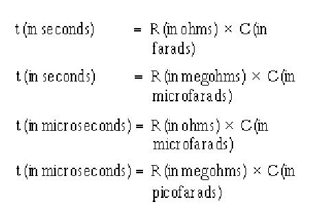
In theory the CD cap can recharge to 86.5% in as little
as .6 usec given an upper FET on resistance of .3 ohms. Lower
FET on resistance is available. It takes the e-shaft 222 usec to
rotate 10 degrees at 7500 RPM. That gives me at least 100 usec to recharge
the cap if I wanted to use just one cap, one totem pole circuit and
one coil per spark plug. That is two sparks every 10 degrees.
If I wanted to go to the waste spark coil for the trailing
plugs and one totem pole I would have 4 mses or 4000 usec
so I could still fire four times using 888 usec. That
still gives me over a millisecond to recharge the caps.
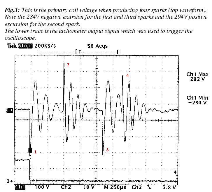
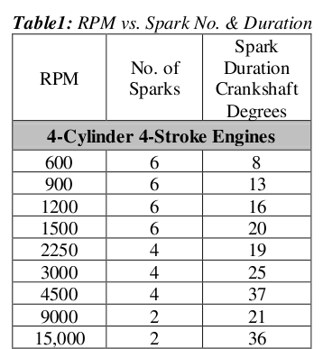
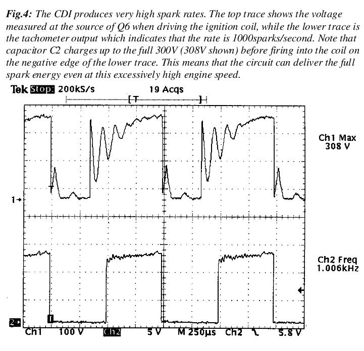
Here are some scope pictures for the Aussie system using
an IRF822 FET with a 3 ohm on resistance.
Also the number of sparks for a 4 cyl which I think
we can do better.
Paul Lamar
--
The Rotary Engine NewsLetter. Powered by Linux.
ACRE NL web site.
http://www.rotaryeng.net
Youtube key word PaulLamar2
Copyright 1998-2010 All world wide rights reserved.