Paul,
I am finally getting around to doing drawings and ordering parts for the
Bell 47 like PSRU.
Do you know where I can get the dimensions of the height of the pilot
boss as well as the bushings? Perhaps someone on here can measure
Tracy's and tell me. Also where to buy the bushings?
Thanks
Doug in Japan
This is all I have right at the moment. I'll try
to remember to measure the height of the pilot
boss next time I am at the hangar.
Did you try AC Spruce for the flange inserts?
Also try Sensenich. They seem to be experimental friendly.
Paul Lamar
Paul,
I found out this info from an aviation talk group. About
bushings source - still no luck with the thread type with
flange. I imagine they are hot pressed in place. Hub
thickness is still an unknown. No lightening holes in mine. I
heard one person say thickness equals 0.41" for a IO-540 and
thats is about 10.4 mm. Mama mia!! That is overkill for forged
4130. The Bell 47 prop shaft OD diameter is 3" so on a SAE #2
the overhang is less than 1.5". 6 - 7 mm thickness should be
adequate. And yes the shaft will be VERY hollow.
SAE AS127D --- it is a grand total of 3 pages.
The following is a summary:
SAE #1 0.375, 4.375, 5.5, 3.38, 0.624, 6, .375-24UNF-3A, 0.500, 0.500, 0.500
SAE #2 0.375, 4.750, 6.0, 3.50, 0.624, 6, .375-24UNF-3A, 0.500, 0.500, 0.500
SAE #3 0.375, 5.250, 6.5, 4.00, 0.624, 8, .375-24UNF-3A, 0.500, 0.500, 0.500
The format of the above numbers is:
Bolt Dia (in), Bolt Circle Dia (in), Flange Dia (in), Prop Thickness (in),
Drive Bush Dia (in), Number of Bolts, Bolt Thread, Drive Bush Height (in),
Bolt Minimum Thread Length (in), Max Distance of End of Bolt From Face of
Hub (in)
Generic Dimensions:
Radius on Corners of the Drive Brushes and Flange 0.03-0.06
Main Flange Centre Boss 2.248-2.250 Dia OD and 2.007-2.009 ID,
1.000" Height above the flange.
Radius between flange and center boss 0.190" Max
Radius on upper corners of center boss 0.03-0.06"
Cheers
Doug in Japan
--
Thanks for the prop flange info Doug. I'll put this into
the SAE prop flange folder for future use.
The reason the flanges are so beefy is the gyro reaction
on a 50 pound constant speed metal prop during a one radian
per second stall or spin is 600 foot pounds. Cut it down at your
own risk depending the the weight and diameter of your prop.
That is also one reason prop shafts are in the 2 inch diameter
hollow or other wise range.
In a helicopter this gyro reaction is negated by hinging the
blades in such a fashion they are isolated from gyro reactions.
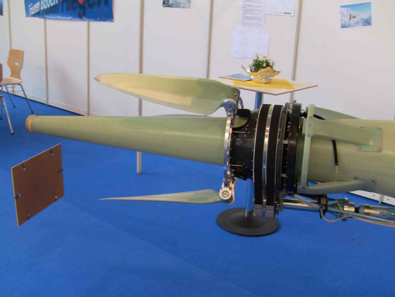
Some motor glider folding props do essential the same thing.
Here is a picture of one I took at Aero this year. Centrifugal
forces open the blades when it spins.
Ironically the IVO was criticized for having flexible blades but
in effect it is easier on the prop shaft. Unfortunately they
were not strong enough to resist torsional vibration and they
would crack until beefed up.
Paul Lamar
--
The Rotary Engine NewsLetter. Powered by Linux.
ACRE NL web site.
http://www.rotaryeng.net
Youtube key word PaulLamar2
Copyright 1998-2010 All world wide rights reserved.